Optical Fiber Adapters and Connectors
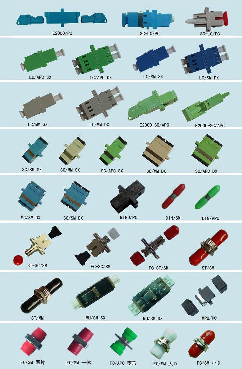
Most Common Optical Fiber Connectors
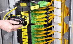
Optical cross connect cases are characterized by the optical fiber adapters used (or if we put it simply – optical sockets). There are also multiple standards and sub-standards.
A standard is a set of an optical fiber adapter (socket) and connector (plug). Of course, there are adapters that are connected within different standards; however, these are kind of crutches – they are only suitable for measurements and should be avoided in a constantly operating communication line. The fewer any spliced and especially mechanical joints in the line, the better. Of course, if the distance is small, the line will work, even if a couple of decibels will be lost on some of the crosses. With short lines, optical attenuators are sometimes specially used. However, for very long lines where the equipment works to the limit, adding one more cross or closure (that is, some 0.05-0.1 dB of loss) can be fatal: the line will not work.
The tip of the “plug” is, roughly speaking, a cylinder with a thin through hole for the fiber in the center. The end of this cylinder is not flat – it is slightly convex. The tip is made of the cermet material, which is extremely hard and resistant to fatal scratches; however, metal tips are also used, very rarely. Rumor has it that people were breaking their side cutters trying to bite through these tips. In spite of this, tips must be handled with care, not allowing for the dust to ingress, not touching the end of the connectors with a finger, and if you do touch it, you need to wipe the tip with an alcohol wipe. Ideally, a special microscope (optical or the one with a camera) is used to monitor patch cords. If a patch cord is dirty, you need to clean it; if it is scratched and the scratch crosses the center where the fiber is, you need to write it off or send it for polishing. Dirty and scratched sockets and patch cords are a common cause of attenuation in the line.
The optical fiber is fixed in the tip by gluing with epoxy glue (or some other glue) and by subsequent polishing on a special device, although this is only done if you need to make long non-standard patch cords: it's easier and cheaper to buy ready-made.
FC Optical Fiber Connectors
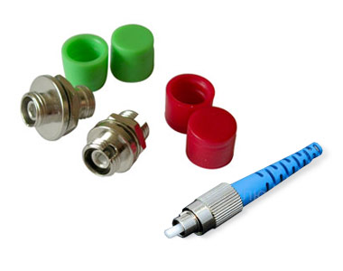
Pros: Excellent connection quality; therefore, suitable for critical backbones. Old proven standard. Metal (hard to break). If you move a well-screwed connector with your hand, it will not adversely affect the connection. Cons: Long to twist / spin when cross-connecting and switching. If they are closely spaced on the cross connect case, it can be difficult to squeeze yourself to unscrew a connector in a crowd of other connectors.
The optical fiber connector itself is fixed securely due to the groove on it and the notch on the adapter, and you can only rotate the knurled nut with your fingers.
The contact side of the tip is not flat; it is slightly convex (this also applies to other standards), so that two fibers from two tips on the opposite sides of the outlet (pigtail and patch cord) are guaranteed to be connected without air and dust in-between.
The socket contains a hollow, thin-walled ceramic cylinder with a split cut. When a plug is inserted into the socket, the cut is widened by some microns, spring loading and centering the plug. In this way, a precise alignment of two connectors in the socket is achieved (remember that the signal is transmitted over a fiber core of 9 μm in diameter and a shift of even 1 μm causes signal loss at the outlet and parasitic reflection). Therefore, dust and dirt are destructive for optical cross connects; patch cords and pigtails must be regularly wiped with a lint-free alcohol wipe, and the sockets should be blown with compressed air or cleaned with special cleaning sticks. A common cause of communication failure is the broken ceramic insert in the socket.
To ensure that connectors press against each other in the socket, the cermet tip in each FC and FC/APC connector (whether it is a patch cord or a pigtail connector) is spring-loaded and can be pressed into the plug by about 1 – 1½ mm. In SC, LC, ST standards the whole plug is spring-loaded, and in ST standard the fixing element is very similar to the one used in local networks with the thinnet coaxial cable.
SC Optical Fiber Connectors
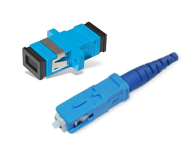
The same as in FC, with the only difference that the adapter and connector are square, plastic and the connector is fixed by snapping, not by screwing. Pros: less expensive than FC, more convenient and quicker when cross-connecting and switching. Cons: plastic is easier to break, less connection-disconnection resource. It sometimes happens that the amount of reflection and attenuation on the connection changes noticeably after touching the connector when it is connected, which is undesirable in critical backbones. Connectors are usually blue in color.
LC and LC Duplex Optical Fiber Connectors
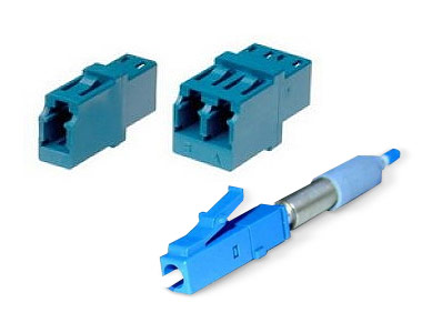
Properties similar to SC properties, but they have much smaller dimensions: an LC two-unit cross connect accommodates as many as 64 ports, and an SC cross connect – only 32. Due to small dimensions, they are often mounted directly on optical multiplexer boards.
FC/APC, SC/APC, LC/APC Optical Fiber Connectors
Same as FC, SC and LC, but with the APC (Angle Physical Contact) polishing.
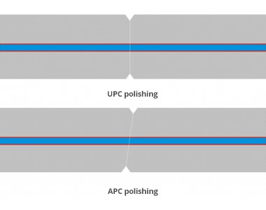 Difference between ceramic tips with UPC and APC polishing. The image is a little inaccurate: in fact, with both types of polishing, the ends are not flat, but slightly convex; therefore, when being connected, only tip centers will touch (where the fiber is).
Such optical fiber adapters and connectors are made in green and when comparing them with conventional UPC polishing (or simply PC), you can easily see the difference. This is necessary to reduce the back reflection at two connectors’ junction. This type of polishing was developed to broadcast analog television via an FO channel, so that there was no image doubling on the screen.
"Conventional" and "angle" polishing connectors can be connected only if it is necessary to make the fiber trace following the principle “The only thing we need is to see the path length": a large air gap will result in substantial losses and strong back reflection.