Optical Testers and OTDRs
Page Content
Optical Time Domain Reflectometers
An optical time domain reflectometer (OTDR) is usually a computerized measuring device whose operation is based on sending pulses to the optical link and analyzing what is reflected with the fiber back-scatter and reflection from irregularities. There also exist reflectometers for copper cables, but we will only consider the optical ones. Reflectometers are expensive and sophisticated electronic devices. For those who are engaged in optical communication, the OTDR is very much needed and virtually indispensable. It's like a dial-up tube for a telephone operator or a LAN tester for an SCS installer: you can do something without it, but troubleshooting will cause a lot of trouble; in addition, the OTDF trace must be attached to the documentation for the constructed communication object.
With the help of a reflectometer we can see the total length of the duct, define the general attenuation and attenuation per kilometer, find the damage, often find a fault in splicing as well, and evaluate whether the closures are well-spliced all over the fiber or whether there is any bend / bad cross junction.
Reflectometers vary, from the easiest ones to measure ducts at short distances to complex multifunctional modular measuring systems for long ducts. There are special-purpose OTDRs, for example, with Brillouin scattering, which will show us where an increased tension is applied in the optical fiber. There are complexes for measuring different types of dispersion on long lines. There are stationary complexes of online line monitoring, whose capabilities exceed the conventional reflectometer.
We will consider simple general-purpose reflectometers.
If you do not take into account any horse-and-buggy reflectometers or primitive “sorry excuse of” reflectometers indicating only a distance to the nearest damage, then the current reflectometer has a measurement result – it's a small file in the format .sor, .trc or in some other format. It can be opened both on the OTDR itself and on the computer by the corresponding program.
Most OTDRs store in the .sor format, EXFO reflectometers and, perhaps, some others use the .trc format. The reflectogram is, roughly speaking, a graph of the dependence between attenuation (the ordinate axis) and the line length (horizontal axis). It should be understood that the reflectogram is not a mathematical abstraction, but a reflection of what is happening in the line, and you can see quite a lot of interesting things on it.
What can a modern universal reflectometer do?
a) Capture the trace in automatic and manual modes.
b) On the integrated display, it can view them, analyze them, immediately recognize the attenuation in a particular area of interest, at the junction (splice closure or cross), and also the length of the line (all or the part we need).
c) Has built-in flash memory, as well as a USB port for the USB flash drive and a file manager to transfer the reflectograms. Old OTDRs could have a floppy disk reader, a COM port, and other interfaces for the same purposes.
d) It is often the case that there are built-in functions of the optical tester, it is very convenient and really necessary.
e) It is often the case that there is an optical socket with a red light source (as in a laser pointer) for visual continuity (or, more accurately, the transmission) of fibers at short distances (up to about 5 km). These are usually called VFL. They help in finding "crosses", bends of fibers in cassettes and broken fibers, and just help to quickly find the right fiber in the bunch.
f) There may be a built-in tester for digital streams and other features.
g) Can work without a network due to built-in batteries.
h) The attached software for the computer can make a ready report on the measurement, with a picture of the trace and trace parameters.
i) Sometimes it is possible to connect additional modules and accessories, for example, a microscope with a camera and backlight to monitor the condition of the ends of the connectors for patch cords and pigtails.
j) If the platform is modular, you can install various modules in the “cart”, which we will need: for example, a module of the OTDR and some module for testing digital streams.
OTDR characteristics & features
The size of modern OTDRs varies: from the size of a large smartphone to a small suitcase.
In addition, there are OTDR modules that can be connected to a computer.
Control methods also differ: some models have a touch screen, others have buttons, and some of them even have a keyboard.
As for architecture, this is usually ARM with Windows CE, although there are OTDRs using Windows XP. Perhaps there are other operation systems.
As for the body, many models are rubber sheaved and have splash protection, to be used in the field. This, of course, is a plus, but dropping an OTDR is still a bad idea. Some models have a built-in cooler.
And, finally, the most important classification is by the measuring module, by its sensitivity, or by the magnitude of the dynamic range. This is what determines the device price to a great extent.
Inexpensive OTDRs have a narrow dynamic range (an approximate analogue is the ISO in the camera), which means that they cannot measure a long line (it is normal not to take a picture of a contrasting or dark scene), or it will take a long time to deal with the settings and wait for a very long time (and still the end of the line on such a reflectometer is lost in noises). Accordingly, if we find a route with very poor splice or a very dirty cross connection, we will not notice anything about this bad connection using an inexpensive OTDR, while with a sensitive OTDR there is a chance that we will have enough range, even if there are noises, and will see what happens next after this bad splice. Also, with inexpensive OTDRs, the trace (reflectogram) itself turns out to be noisy and uneven when magnified: there is small attenuation on a well-spliced closure or a small crack can simply not be noticeable, and when it is necessary to find all splice closures on the duct and find distances to them and between them, this becomes a problem. In addition, inexpensive OTDRs have quality issues with both software and manufacturing. Software can not only cause strange annoying glitches, but can also directly interfere with measuring, by drawing an incorrect trace and thus misleading the operator.
Expensive OTDRs, respectively, allow you to quickly and accurately measure long lines; they do not offer nasty surprises, allow you to repeatedly get well-measured, accurate, informative reflectograms.
Frequent spontaneous shutdowns, reboots and re-settings. Sometimes the device fails to find the OTDR module (that is, the module of the OTDR itself) after a cold start, or simply does not complete the download at a certain stage; however, if the device is put into sleep mode after this error and started again, everything is back in place. However, sometimes it is not: one day my colleague went to another city on a business trip and the device wouldn’t load there, so he had to use the device of a local team. Upon his return, the device started working again. Sometimes the glitch is seen in the measurements results as well, sometimes it's so complicated and confusing that it's not even easy to formulate a bug report ... It's easy to get deceived and to wrongly determine the distance to the line break, so you may go looking for a line break in the wrong direction: the reflectogram is drawn OK, but it is performed faster than usual and looks somewhat crooked, and it is difficult to guess that it's a glitch, especially if you do not have experience with such a crafty device)) The following will most likely happen: after a few normally drawn reflectograms, the settings are reset to default, including the set range of length (and the default range is 300 or 500 m on different firmware), the OTDR begins to reflect and draw what it sees on these 300 meters, but somehow shows noise, which is similar to the end of the line ... Or it can be this way: on a smaller scale everything is fine, and when the scale along the length is made a pinch less, then the working area of the reflectogram in general is drawn somewhere outside the permissible region vertically, and it simply does not exist in the trace (reflectogram) file; you can only see the beginning of the line, the final peak and noise. With automatic analysis it can show one length of the line, and when manually setting the cursors, it shows exactly the beginning and end of the line, and the length of the line will be slightly different.
Popular OTDR Models
Yokogawa AQ7270 (and similar Yokogawa models). This is a good device from Japan used by many customers, yet not without flaws.
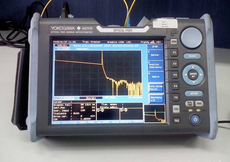
Pros:
- High quality of received reflectograms.
- Although the device does not have a touch screen and there are many buttons, you quickly get used to it.
- The body is rubber sheaved.
- Good reliability, high quality.
- You can configure the macros for automation: one click will allow for full measurement at two wavelengths, as well as storing and naming one fiber.
- There is a red VFL (visual fault locator).
- There are many models with modules of different dynamic range, accordingly, the price differs.
Cons:
- High price.
- Large dimensions and weight.
- Software is not fully perfect: sometimes it can pick up a trace with strange glitches or indicate the existence of non-existent events.
- Touch screen is not sufficient.
EXFO FTB-200, revision one.
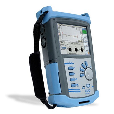
This is an excellent, but very expensive professional device from Canada. It is a module platform with 2 modules. The device offers a touch screen, an excellent quality of reflectograms, optical microscope connection, a lot of possibilities, and excellent dynamic range. The package includes a long-lasting bag. Disadvantages include a large size and weight (the device is the size of a small backpack and the bag is the size of a normal backpack), a fan. The first revision is already outdated. The second revision is of the same level, but has changes corresponding to the modern realias.
EXFO FTB-100.
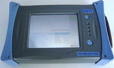
This is also a good OTDR, but already very outdated: the device is still from the 90ies. It has a large touch screen, but there's also a floppy drive and a COM port. There is no USB port. Feels like FTB-200.
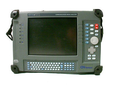
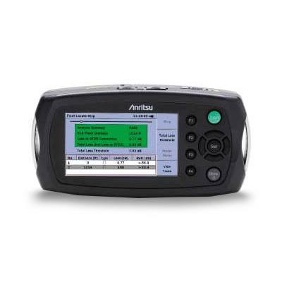
There exist lines of OTDR models by other companies: Fluke, FOD, Anritsu, Fujikura, NetTest, and others.
Optical Testers
An optical tester is an electronic digital device for optic measurements. It is generally cheaper and simpler than an OTDR, although a tester of high quality or of a recognized brand can be much more expensive than a simple reflectometer.
First of all, the tester is needed to show the received signal power (in dB, in dBm or in W), and it also operates as a transmitter for another tester at the far end of the line. However, there are relatively inexpensive sources of optical radiation at 1310/1550 nm, if only a source is needed, not a full-fledged tester.
Some testers can have additional features: a color screen, the possibility of connecting a microscope camera to monitor the ends of patch cord and pigtail connectors, the presence of a built-in primitive reflectometer, different types of modulation of the emitted signal. Some testers can only work with the wavelengths of 1310 and 1550 nm, others allow you to set the wavelength smoothly, within the accuracy of a few nanometers, by measuring the line attenuation at wavelengths outside the fiber transparency windows.
How bad do you need a tester? Not as much as a reflectometer, but it is still irreplaceable. According to the documents, the duct (or the cable at input control) must be measured both with a reflectometer and with a tester, but the customer can only be satisfied with the reflectograms, and these are usually quite enough.
There should be two testers: one sends a signal to the line, the other at the far end looks at what level the signal comes. However, since OTDRs often have the functions of a tester, it is possible to put an OTDR as a transmitter on one side, and to make a tester a receiver, or vice versa. Operators usually do it this way.
The tester can search for tangled fibers, crosses and generally perform a continuity test to define which port of cross connect A connects to which port of cross connect B. If the distance is small, it can be done visually by a red VFL laser (I also recommend buying such a "pointer" with an optical socket on the end, if your tester / reflectometer does not have a built-in "backlight"). However, the red light passes maximum kilometers 5-6 and then attenuates (because the wavelength does not fall into the fiber transparency window); then the tester becomes irreplaceable.
Popular optical tester models
An example of a good tester is the Canadian EXFO FOT-930.
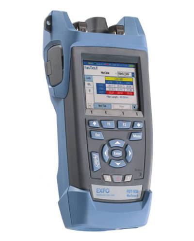
You can do quite a lot of things with it, for example, you can connect a microscope module to it and see on the screen how dirty and scratched the end of the patch cord is. There is a "FasTest" function of auto-measurement. Among disadvantages are rubber optic fibre cable blanking plugs, weak ports of the microscope, which are quickly decayed. With its price, those who serve first-class optical backbones and constantly measure them need this device as a rule.
How do you measure a line with testers?
One tester will be a transmitter, and the other will be a receiver. We connect them with clean patch cords via a clean socket (i.e., by the chain "transmitter port – patch cord 1 – socket – patch cord 2 – receiver port"), turn on, adjust to the same modulation, the same units of measurement and the same wavelength, and see what the receiving tester shows. This is our "reference zero", you can even reset the receiver's settings so that this reading is considered the reference zero. Then, when the transmitter is turned off, the receiver will show a strong "minus". Next, we turn off the testers, disconnect the two patch cords on the socket, do not forget to cover the patch cord connectors with clean plugs, and without twisting off the other side of the patch cords from the device (so that not to introduce an extra error – when the patch cord is loosened / twisted, the attenuation will fluctuate from time to time!) We carry the transmitter to one end of the line, and the receiver – to the other, connect to the line (after cleaning the sockets and pigtails in the cross connects) and perform a measurement.
The receiver will show some negative value (in decibels). When the receivers were nearby and 100% of the power came from the transmitter to the receiver, we showed that this is the reference zero. Now a part of the power is lost in our line, and the negative value on the receiver is the attenuation of our entire duct. If we divide the value by the optical length of our duct, we will get attenuation per kilometer (in dB / km).
We make measurements at both wavelengths, 1310 and 1550 nm and record the results in a notepad. Then we repeat the process for next fibers. If you like accuracy, you can swap around the devices (or switch the transmitter tester to receiving transmission, and the receiver to transmission), then try again and take the average value. This way of measuring the line attenuation by the testers is most accurate, but very uncomfortable and time-consuming. Usually, the main backbones are measured once a year by both testers and reflectometers in both directions, and when measuring simple lines operators do not usually bother to use a tester and are content with a reflectometer (measuring in one direction), or they even measure something only when communication fails. When measuring with a reflectometer, there are some subtleties, but the overall quality of measurement is quite good.