Digital Oscilloscope + Transistor Tester FNIRSI DSO-TC2


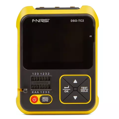

FNIRSI DSO-TC2 is a portable and compact digital oscilloscope with built-in ESR tester and PWM signal generator. Equipped with a large-size color dot matrix TFT display. Powered by a built-in rechargeable lithium battery.
FNIRSI-TC2 has various working modes such as oscilloscope and component tester. Each time you click the power button, you enter the mode selection interface. Press the [Up] and [Down] keys of the direction keys to select. Select “Mos Test” item, press [OK] key to enter component tester mode. Select the “Oscilloscope” item, press [OK] key to enter the oscilloscope mode.
"Mos Test" mode can test various types of transistors, and can identify device type, pin polarity, hFE, turn-on voltage, junction capacitance; can test capacitance, resistance, inductance components, etc.
FNIRSI DSO-TC2 is especially suitable for fast pairing of transistors, identification of mixed surface mount components, and preliminary screening of small batch components. "Oscilloscope" mode is designed to test the signal waveform of the circuit.
Features
- 2 in 1 device integrates digital oscilloscope, electronic component tester, PWM signal generator and other functions into one.
- The oscilloscope has a real-time sampling rate of 2.5 MS/s and a 200 kHz bandwidth.
- With complete trigger function (Single, Normal, Automatic), it can be used freely for both periodic analogs signals and aperiodic digital signals.
- Up to ±400V voltage signal can be measured.
- Equipped with efficient one-key AUTO, the measured waveform can be displayed without cumbersome adjustment.
- Self-contained 80kHz /5.0V PWM waves test signal source with adjustable duty cycle.
- This device can automatically identify and measure various transistors. Including NPN transistors, N-channel and P-channel field effect transistors, junction field effect transistors, diodes, double diodes, thyristors, etc., and passive component such as resistors, inductors, capacitors, etc
- Automatic detection of pin definitions.
Technical Specifications
| Oscilloscope Mode | ||
|---|---|---|
| Real-time sample rate | 2.5 MS/s | |
| Analog bandwidth | 0 ~ 200 kHz | |
| Input resistance | 1 MΩ | |
| Coupling | AC/DC | |
| Test voltage range | 1:1 probe: 80 Vpp (±40 V) | |
| 10:1 probe: 800 Vpp (±400 V) | ||
| Vertical sensitivity | 10 mV/Div ~ 10 V/Div (in 1-2-5 increments) | |
| Vertical displacement | adjustable, with indication | |
| Horizontal time base range | 10 μs/Div ~ 500 s/Div (in 1-2-5 increments) | |
| Trigger mode | Automatic, Regular and Single | |
| Trigger type | Rising edge, falling edge | |
| Trigger level | Adjustable, with indication | |
| Waveform freeze | Yes (HOLD function) | |
| Automatic measurement | Maximum, minimum, average, rms, peak-to-peak, frequency, period, duty cycle | |
| PWM output | FRQ: 0 ~ 80 KHz, Duty cycle: 0 ~ 100%, Amplitude: 5.0 V | |
| Transistor Detector | ||
| Category | Scope | Technical Parameter |
| Triode | + | Magnification hfe, base-emitter voltage Ube, Ic/Ie, collector-emitter reverse cut-off current Iceo, Ices, protection diode forward voltage drop Uf |
| Diode | Forward voltage drop <5 V | Forward Voltage Drop, Junction Capacitance, Reverse Leakage Current |
| Zener diode | 0.01 V ~ 4.5 V | (1-2-3 test area) forward voltage drop, reverse breakdown voltage |
| 0.01 V ~ 24 V | (K-A-A test area) reverse breakdown voltage | |
| FET | JFET | Gate capacitance Cg, drain current Id at Vgs, protection diode forward voltage drop Uf |
| IGBT | Drain current Id at Vgs, protection diode forward voltage drop Uf | |
| MOSFET | Turn-on voltage Vt, gate capacitance Cg, drain-source resistance Rds, protection diode forward voltage drop Uf | |
| SCRS | Turn-on voltage <5 V, gate trigger current <6 mA | Gate voltage |
| Triac | ||
| Capacitance | 25 pF ~ 100 mF | Capacitance value, loss factor Vloss |
| Resistance | 0.01 Ω ~ 50 MΩ | Resistance |
| Inductance | 10 µH ~ 1000 µH | Inductance value, DC resistance |
| Battery | 0.1 V ~ 4.5 V | Voltage value, positive and negative polarity |
| Input voltage | 0 ~ 16 V | Voltage value |
| Temperature (DS18B20) | + | Temperature |
| Humidity (DHT1) | + | Humidity |
| PWM output | 1.5 kHz ~ 9.99 MHz | * |
| Infrared remote control decoding | NEC protocol infrared code | Display user code and data code, and display the corresponding infrared waveform |
| General Specifications | ||
| Display | 2.4 inch TFT color screen, LED backlight | |
| Powered by | 1500 mAh rechargeable lithium battery | |
| Charging | USB Type-C,+5V | |
| Dimensions | 79 mm × 31 mm × 103 mm | |
| Weight | 296,6 g | |
User Manual
![]() Download FNIRSI DSO-TC2 user Manual.
Download FNIRSI DSO-TC2 user Manual.
Package Contents
- Digital Oscilloscope + Transistor Tester FNIRSI DSO-TC2 — 1 pc.
- User Manual — 1 pc.
- Type-C Cable — 1 pc.
- Component Test Probe — 1 pc.
- Packing Box — 1 pc.
- Adapter — 1 pc.
- Standard Oscilloscope Probe — 1 pc.
| Number of channels |
|
| Type |
|
| Bandwidth |
|
| Screen Size |
|
| Sample Rate |
|