
31.07.2023
Page Content
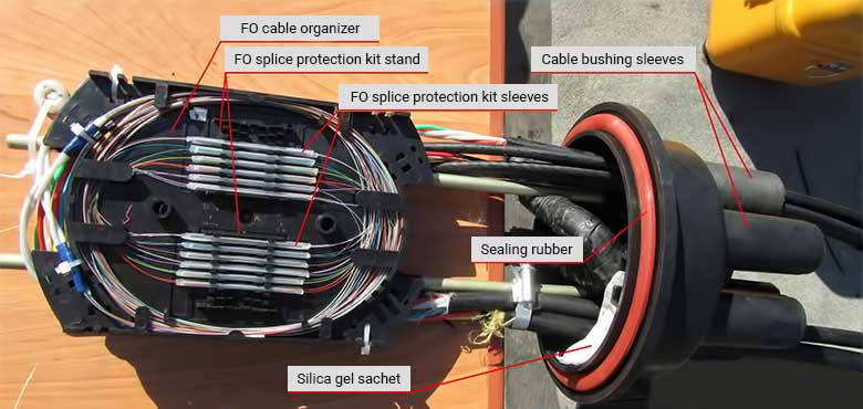
A fiber optic splice closure is a plastic container, where cables are brought into and connected. In the past, in the late 90s and early 2000s, when all specialized materials for optical fiber were scarce and had jaw-dropping prices, some nimble guys used sewage fittings and plastic bottles as closures. Sometimes these constructions even worked successfully for several years. This definitely sounds absurd today, however, because fiber optic splice closures have become ubiquitous.
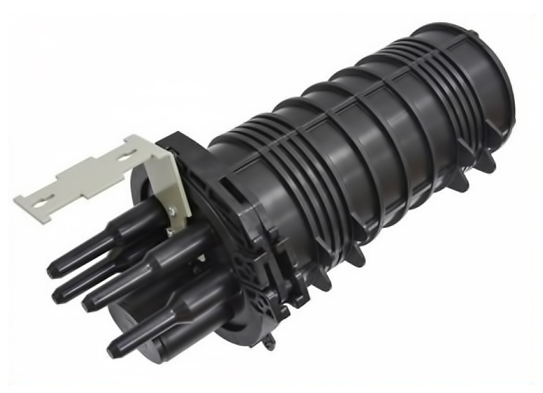
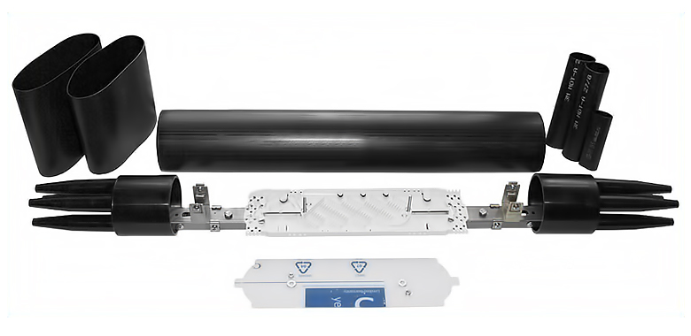
There are many designs for fiber optic splice closures. The most widespread and most often used design has a dome-like container from which cable bushing sleeves are sticking out. Inside the container, there is a metal frame where fiber optic cable organizers are fitted. On the top, a cap is put on (it can have strengthening ribs to make it stronger), sealed with a sealing rubber. The cap is fixed with a detachable plastic clip; in this way, the closure can always be opened and closed without having to use the repair kit with heat shrink sleeves.
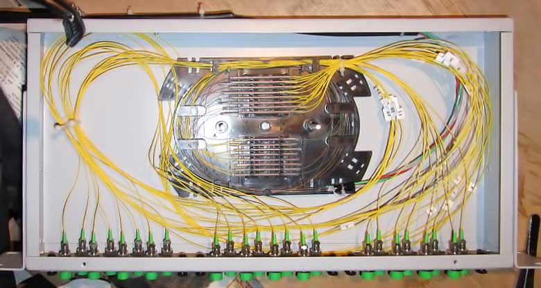
The optical cross connect is intended for terminating a cable in the place where it has been pulled: on a base station, in a data center, in a server room. A typical cross is a metal box sized 19" to be mounted on a standard rack; the cable to be terminated is inserted at the back, and in front there are plates with ports.
 FC / APC single-unit spliced cross connect with 24 ports
 LC two-unit spliced cross connect with 64 ports
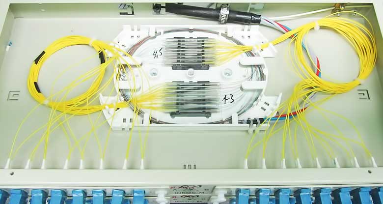
 FC working cross connect with 96 ports
There is a less expensive option – when you take away everything you can from the cross; then it will look like this:
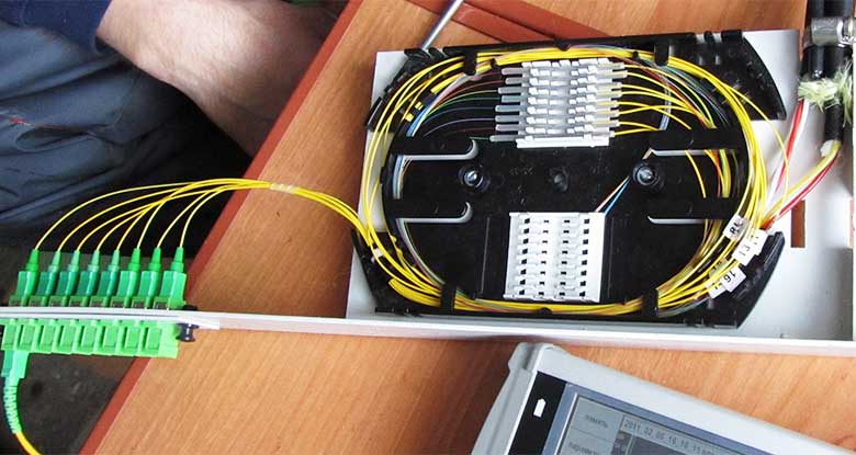 SC / AP single-unit open cross connect with 8 ports. Its drawback is that optical pigtails are not protected in any way and can thus be broken by those who will dig in the box / rack, for example, running a new cable
All these crosses are mounted on a rack, but there can also be FO cross panels, as well as other options that are rarely used. In theory, several cables can be run into the cross connect, some of them can be spliced together, and some can be routed to ports. Then you get something you can call a "cross-closure", in this way saving on materials and splicing. Sometimes this is done when installing FTTB, but doing so is undesirable, as the circuit complexity increases.
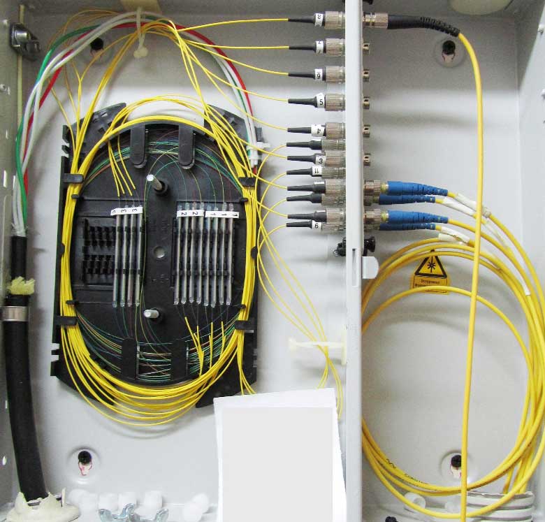 FC fiber optic cross panel with 16 ports. This one is not spliced well: the yellow coating of pigtails does not enter the CDS and fibers can break, while fibers in the organizer are packed with small bending radii
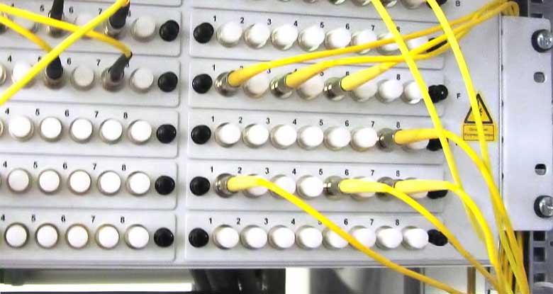
The cable that is put into the cross is spliced with the so-called pigtails: at the photos, these are thin yellow “laces” inside the crosses. Each fiber is spliced with its own pigtail. The other side of the pigtail contains a bayonet fiber optic connector, which is inserted into the optical adapter – socket - from inside the cross. On the outer side of the cross, the patching is performed with optical patch cords (thick yellow cords). The difference between a pigtail and a patch cord is that a patch cord has a more durable connector and Kevlar inside, so that if someone grabs the patch cord and pulls it, it's hard to rip it out. Another difference is that patch cords have connectors on both sides, while pigtails have only one connector on one side. If necessary, a temporary patch cord can be spliced using two pigtails.
In theory, several cables can be run into the cross connect, some of them can be spliced together, and some can be routed to ports. Then you get something that can be called "cross-closure" and save on materials and splicing. This is sometimes done when installing FTTB, but doing so is undesirable, as the complexity of the circuit increases.
