
31.07.2023
Earlier articles dealt with cable termination, wiping fibers, preparing FO splice closures (or ODFs) and pulling the cable into them. We continue installation and need to do something important before the fusion.
Page Content
The next step is to mark or label optical modules and fibers. Be sure to mark the cable before putting it into the splice closure. If you fail to do it, you will need to check which fibers go to which module. It is very inconvenient and it is easy to make a mistake.
For marking, the following paper (or cloth) labels are used.
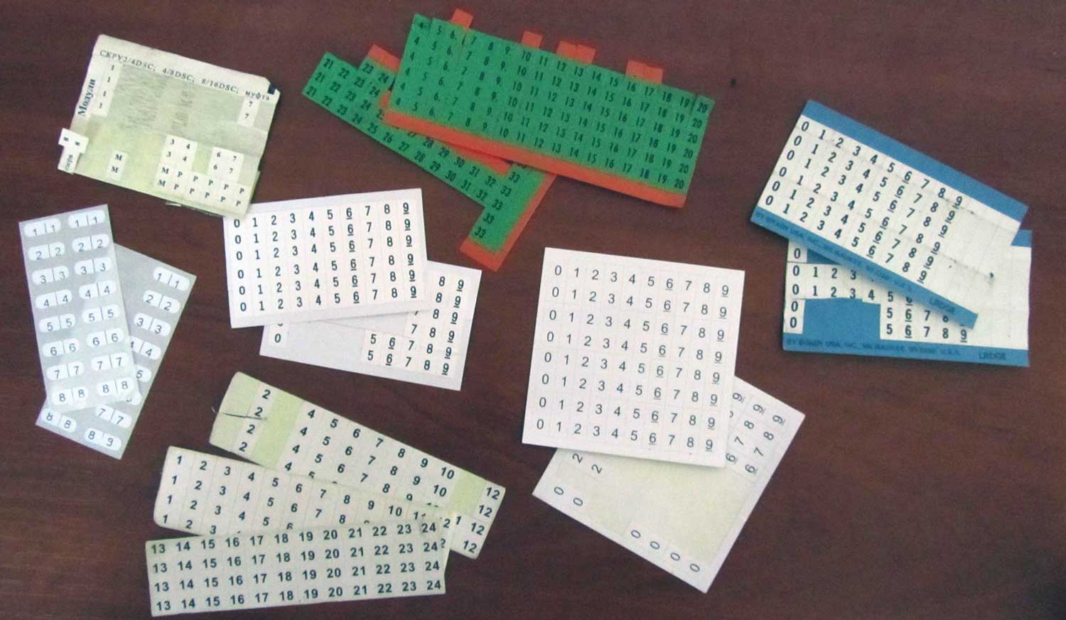
They usually come with the splice closure or – more seldom – with the ODF.
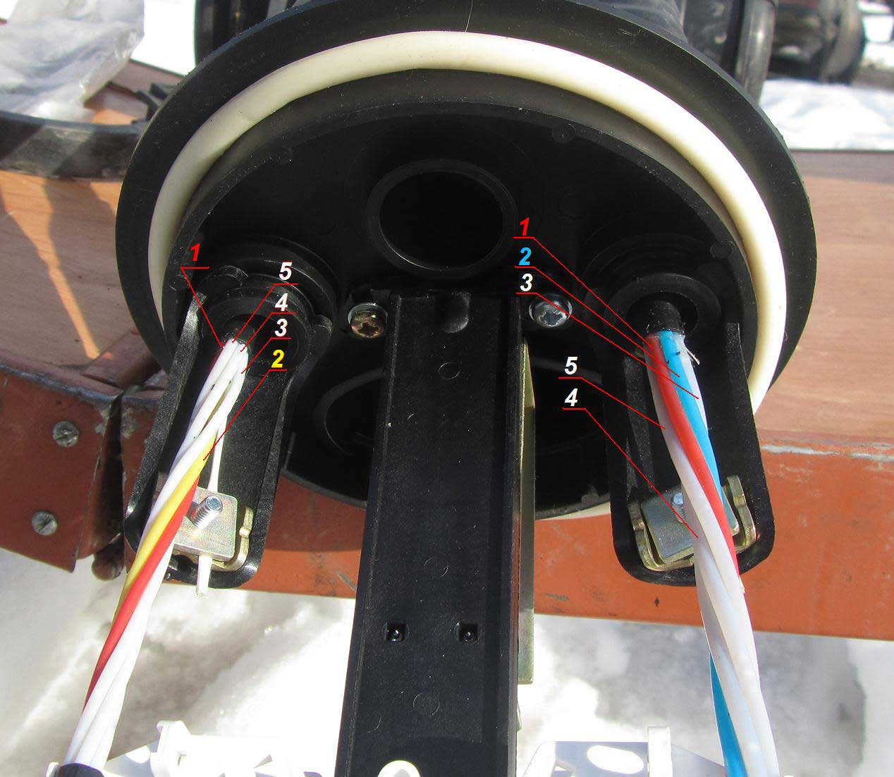
A very common mistake made by beginners, which is also very unfortunate and difficult-to-locate, is to get fiber optic modules mixed up or entangled. Although it is a newbie mistake, experienced technicians occasionally make it too. It is difficult to confuse Module 1 (red) and Module 2, but one may well mix up white / natural / colorless modules, because they are the same color. This is when you can overlook a silly mistake.
The picture below sketches a cut cable, also identifying the labelling principle of its modules. Below it, a real example of marking a cable is shown.
Fiber Optic Cable Module Numbering
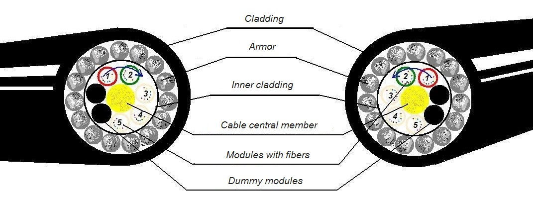
Fiber optic modules are marked in the following way:
They usually are color-coded, which is indicated in the cable passport. Still, Module 1 is always red. You need to attach a label with number 1 to cleaned fibers coming out of Module 1. The next one is another color-coded module and is located next to the red module. In fact, there are two modules located near the red module, one on the left and one on the right, but on the other side there will be either white (natural, colorless), or a dummy module, which can be either black or white. So a color-coded module (usually yellow, green or blue) located next to the red one will be Number 2. Attach label 2 to its fibers.
Depending on the cable, Module 3 can be another color-coded module or a white / natural / colorless one. Here one issue is important. The first two fiber optic cable modules have already provided us with the direction of modules in the cable – either clockwise or counterclockwise. We follow this direction and attach label 3 to the fibers of the next module. The red module is the first one, the color-coded module is the second, and the next in turn is Module 3. Another module following the same direction – usually colorless – is the fourth, and so on.
It seems so easy to understand. However, modules are often mixed up and it is difficult to locate where the confusion occurred and eliminate it, especially when there are a couple of dozens of splice closures in the line that need to be checked, many of them being dug several meters into the ground.
How do you find the place where modules were entangled?
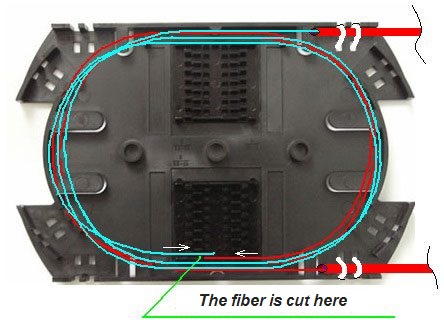
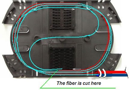
The location of error is determined as follows. Suppose we have a straight line: 2 ODFs and several splice closures between them.
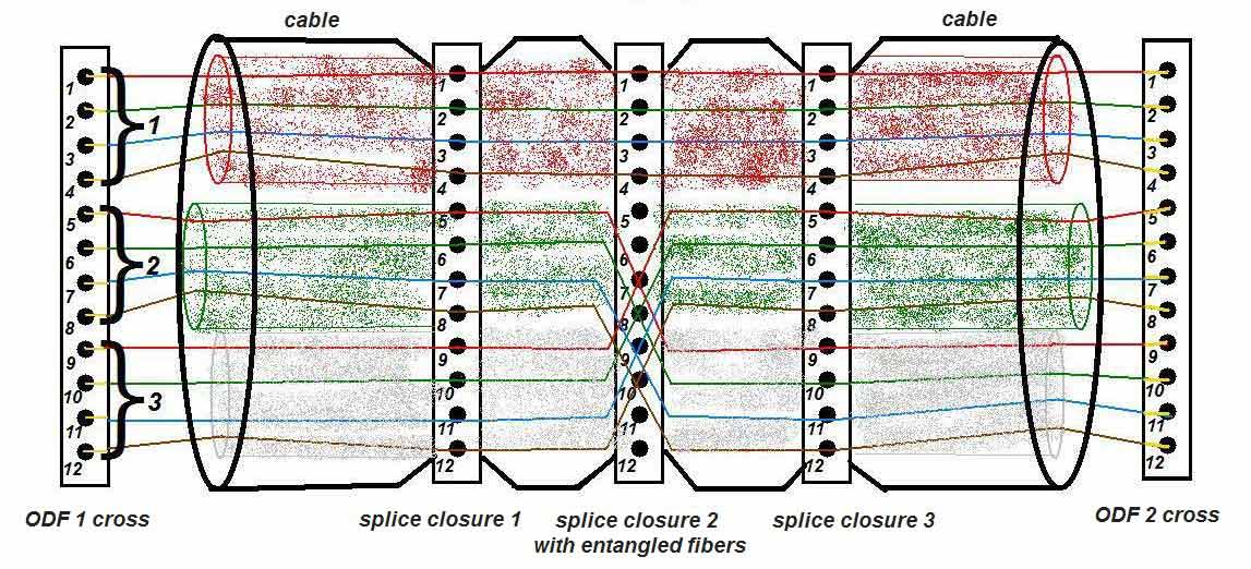 Communication line with entangled fiber
A person carrying a fiber optic transmitter 1310 or 1550 nm wavelength stands at one ODF location; at the second ODF location there is a person with an FO receiver-tester set to the same wavelength. They put both receiver and transmitter on Port 1. If the fibers are not mixed up and the signal from the ODF 1 Port 1 reaches ODF 2 Port 2, the receiver will show a certain signal level. In this way – calling back to each other to coordinate the actions – all ODF ports are tested.
Now let's come back to finding entangled fibers on the fiber optic line. If there is a "cross-over", it becomes immediately clear. Starting from a certain port (at our figure it is Port 5), the next port is just the "transmitting" ODF, and Port 5 on the next – "receiving" – ODF has no signal, but there is a shift of x*n in signal in Port 5 (and subsequent n-ports). This shift can be calculated in the following way: x * n, where n is the number of fibers in the module, x is the number of modules that "leapt" (in our case n = 4 fibers in the module, x = 1 (leap over 1 module). The signal in Ports 1 to 4 passes through correctly, and the signal from Port 5 is transmitted to Ports 9, 6, 10 and so on.
To get it right, you need to open the optical distribution frame and (ODF) sort out all fiber optic splice closures to figure out the error location. Of course, you can simplify the task of finding the root of a problem: open an fiber optic splice closure in the middle of the line and manually check it by pulling through a fiber from each module. Then carefully (to prevent breaking) bend the fibers on one of the modules (say, fiber 1 of module 1, fiber 2 of module 2, etc.), and the colleague who is standing near the distribution frame with a reflectometer will check whether there is a signal loss. Remember that a fiber that is tightly bent loses light at a bend and does not pass the signal further.
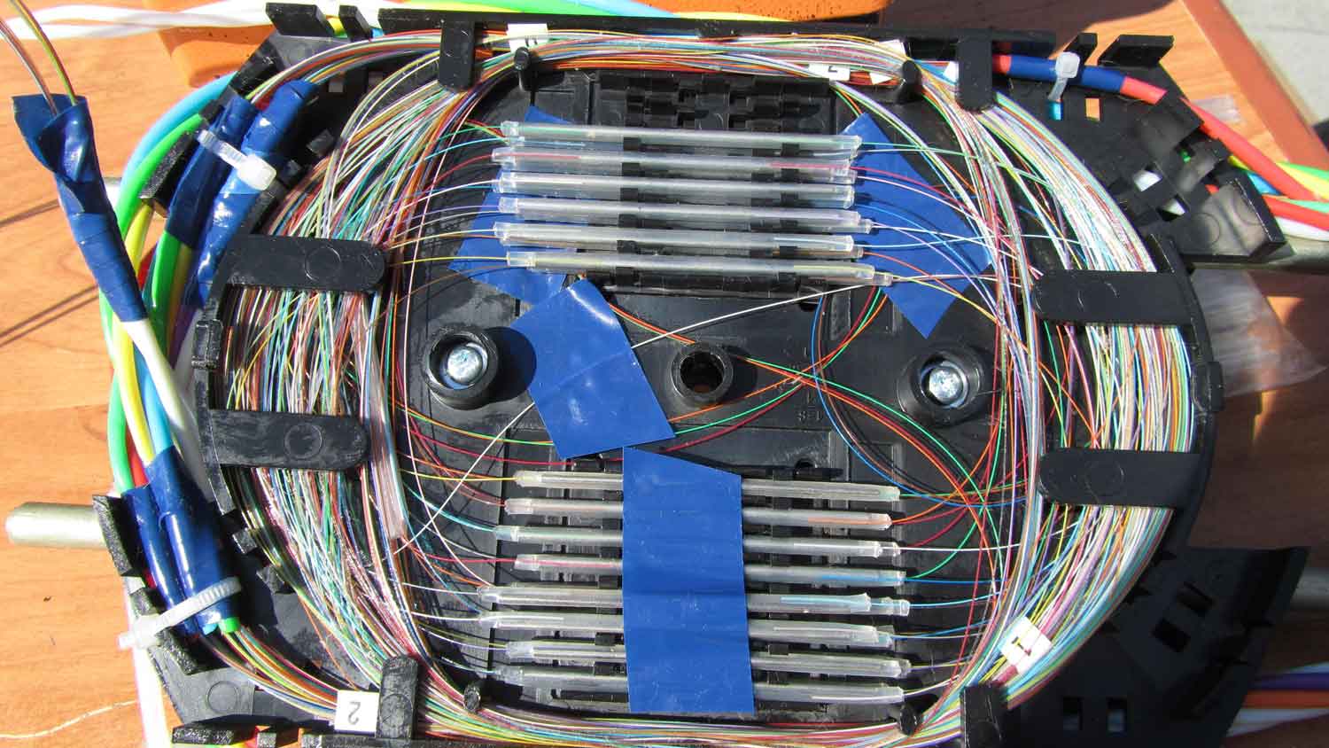
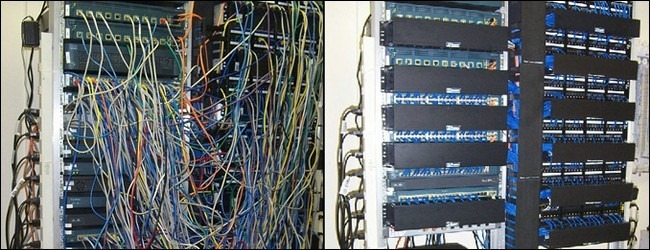
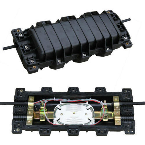 Fiber Optic Splice Closure
If the correspondent fibers in correspondent ports show signal loss after bend, then the error must be elsewhere, between the opened fiber optic splice closure and an ODF located farther. If we bend, for example, a fiber from Module 3, and the corresponding fiber from Port 4 has indicated a signal loss, then the error is in an fiber optic splice closure between the ODF where the reflectometer is placed and the FO splice closure we have just checked.
We close this closure and move further to open a splice closure between the ODF and the splice closure we just checked and repeat the procedure. For such work, it is crucial to have a wiring map and a line diagram, which will indicate distances from ODFs to all fiber optic splice closures.
If the wiring map is complex, the line has a lot of splice closures with transition points, cables have differently colored optical fibers and different number of fibers in modules are spliced, then the task becomes much more complicated. Here you have to brainstorm, use your brain and wrap your mind around the wiring map, developing the best plan to find a splice closure with an error. And if in such a complex line there are 2 or more places where modules are entangled, then ...... technicians need more training before splicing large complex lines.
There may be an easier mistake: when a couple of optical fibers (not modules) are entangled. For example, in poor lighting, you can easily mix up white and gray fibers, gray and colorless / transparent, white and light pink, green and turquoise, etc. At least this is easier to figure out; if the cable organizer of the splice closure has info about the location of fibers and their direction, you can just open the splice closure and can see what color of the fiber is fused by comparing data with the wiring map. However, if the splice closures are hard to reach, it is pathetic.
To sum up, you have seen how unfortunate the error with entangled modules or fibers is, and how difficult it may be to fix it.
We have marked optical fibers on all cables. But if we fuse an ODF, then we do not splice cables with each other, but we fuse one cable making use of pigtails in ODF. I recommend that these pigtails should also be labeled. It is not a must, but if you don’t label pigtails, you will be distracted while fusing – thinking whether you have taken the correct pigtail.
Now that modules / fibers and pigtails are marked, we attach modules to the cable organizer. Please note that you need to have inserted the optical cable into the splice closure beforehand and fastened it with the Kevlar pigtail (using a special clamp, the central member or fastening the cable to the steel frame of the splice closure with the clip). You also need to decide in advance which modules will go into which cable organizer).
The next step is measuring fibers in the fiber optic cable organizer.
You measure fibers putting them in a cable organizer and then cutting with scissors in the center of FSPK cradle where they are planned to be laid after fusion.
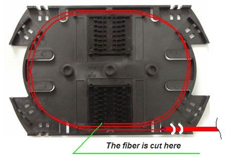
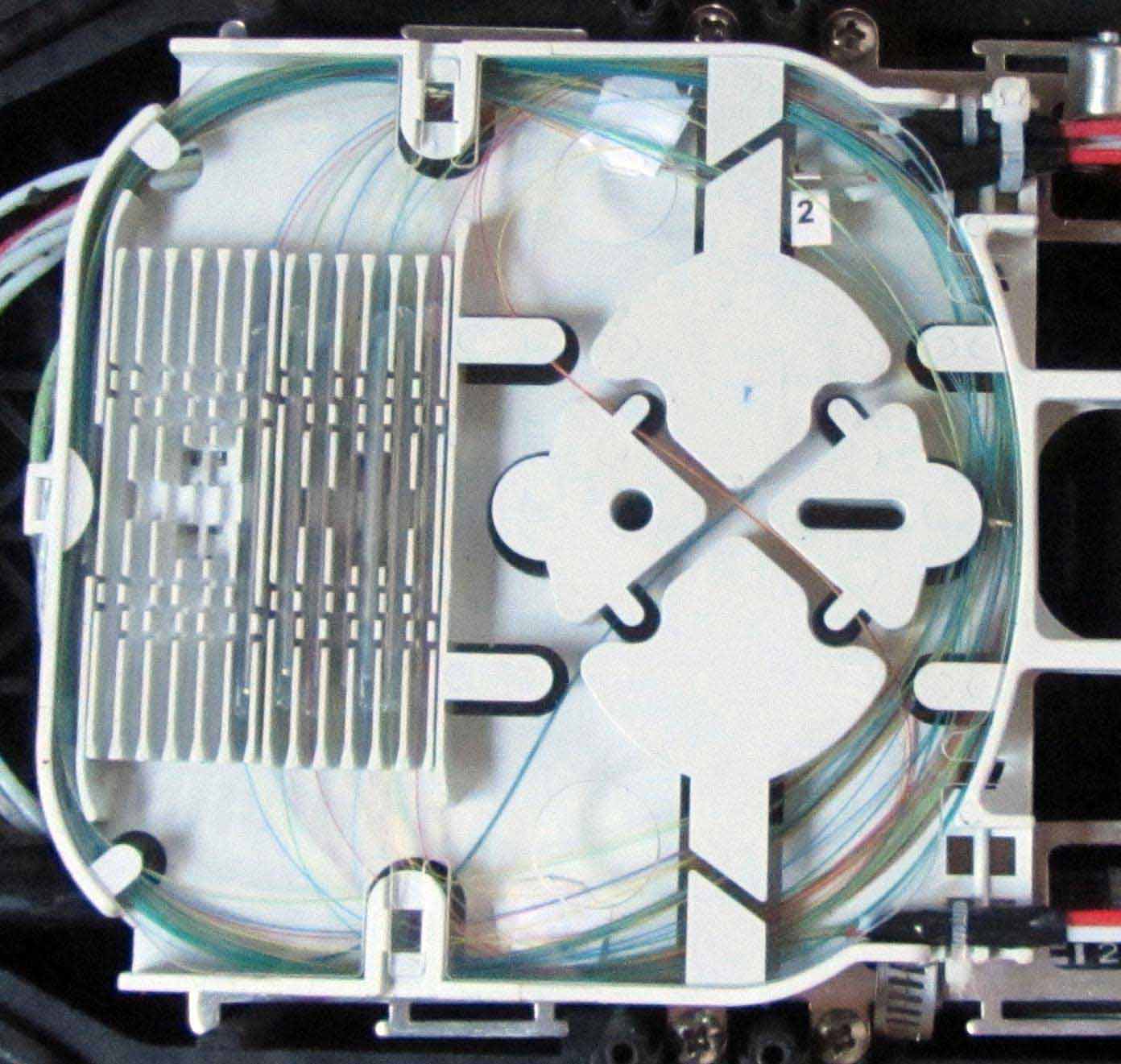
In some cable organizers (for example, as in the picture below), where there are many differently directed channels for fibers, optical fiber measuring does not need to be performed – there will always be a way to lay fibers, so that they are located neatly and beautifully after fusion.
However, when fusing a large number of optical fibers, they should still be measured, and the easiest way should be chosen: in a circle, without tricky complex loops and channel transitions. With most cable organizers, it is necessary to measure out: there will be serious problems when laying fibers unless if you measure fibers in advance and think how they will fit into the cable organizer after fusion. At best, fibers will be laid, but permissible fiber bending radii will be violated, which can lead to an increased signal loss, and the cable organizer will look ugly. At worst, you will not be able to lay fibers to keep the optical cable organizer cover closed with no fibers blocked or clamped.
This is a nightmare that will happen if you forget to measure fibers: some of the fibers are located too tight and therefore are bent too much (there will be attenuation at bends), others are too long and they have to be placed over small radii and fixed with electrical tape.
When two optical fibers that are to be fused are in the modules, which enter the cable organizer "counter" each other, it is enough to measure each of them by simply laying several (usually two) turns and cut off above the cradle, where it is planned to lay the FSPK of this splice.
If the modules go "co-directional" (it happens when 3 cables are fused in one cable organizer), one of the fibers should be measured as usual, and the second fiber should be measured taking into account the S-shaped loop in the middle of the cable organizer.
In general, the above situation with the S-shaped fiber transition should be avoided and you should try to position the modules counter-currently. Firstly, not all cable organizers are designed for such fiber transition and you will need to fix the S-shaped fiber transition loop (and there may be many) in the center with the tape, which is grungy and undesirable. Secondly, it takes more time to measure optical fibers. If the splice closure is complex, if it contains several cable organizers and there are fiber transitions in modules between lower and upper cable organizers, if the wiring map is complex with 3 – 4 or more cables involved, then installation becomes too complicated and you can make a mistake which will be very difficult to find and correct in the future.
We also need to consider whether all fibers that we plan to fuse fit into the cable organizer.
Let's consider some cases.
The simplest case is when you need to connect 2 identical fiber optic cables, with – say – 32 fibers, where there are 4 modules (8 fibers in each module). A typical cable organizer is designed for 32 fibers (or 36 – then 4 places will remain free). FSPK (fiber splice protection kit) where Modules 1 and 2 are connected will be in the lower half of the cable organizer (8 + 8 pieces, in 2 layers, as it was calculated), and modules 3 and 4 will fall into the upper half of the cable organizer. It's simple.
A more complicated case would be with 2 identical fiber optic cables for 64 fibers, 8 modules with 8 fibers in each. Not all of them will fit into one cable organizer; it means that half of fibers will go to the lower cable organizer, half – to the upper cable organizer (cable organizers are put on top of each other). Therefore, half of modules (Modules 1, 2, 3 and 4) of both cables are inserted into one cable organizer, and the second half (Modules 5, 6, 7 and 8) - in the other. Modules are fragile, but if they are fastened in the fiber optic cable organizer well, then the upper cable organizer can always be gently lifted to work with the bottom cable organizer.
You may also ask yourself which cable organizer you should place on top and which on the bottom. In fact, there is no straight answer. One person would fuse the splice closure "from the end side", and then the upper cable organizer would be the beginning, which is logical. Another person would fuse the splice closure in order. It is not so important.
 Cable Management
An even more complicated case is when we need to fuse two different cables that have different number of modules and the modules have a different and variable number of fibers.
Let us look at an example. The first cable (let's call it A) has 64 fibers (8 modules with 8 fibers in each). The second cable (B) also has 64 fibers, but it has 6 modules (with 8 fibers in Module 1 and 2 and 12 fibers in in Modules 3 through 6). What do we do in this case? We need to think carefully about how many splices we will place in each cable organizer, so as not to get confused - the fibers (already marked according to modules) should be further divided into "stacked/laying" groups and marked with pieces of paper with inscriptions. In our specific example, Modules 1 and 2 of cable A with 8 fibers in each are well fused with Modules 1 and 2 of cable B (also 8-fiber modules).
Excellent, there are 16 splices, half of the fiber optic cable organizer is filled. What's next? Module 3 of cable A (8 fibers), and Module 3 of cable B (12 fibers). Our cable organizer is designed for 32 splices; extra 4 will not fit in it. What do we do? Hence, we fuse (fiber colors - according to the wiring map) the entire Module 3 of cable A (all 8 fibers) to a part of Module 3 of cable B (only first 8 fibers), and the cable organizer is full.
And the remaining 4 fibers from Module 3 of cable B, we should withdraw from the filled fiber optic cable organizer on the opposite side and insert them into the next cable organizer, where we will continue to fuse. Between cable organizers, the fibers must go in a plastic tube, which is fixed to the two cable organizers with the cable ties, just like modules. That's how the module is divided into 2 cable organizers.
An even more complicated case is when you have 3-4 completely different fiber optic cables and absolutely insane wiring map, plus you need to work at night (you were not allowed to have people cut off in the daytime – unfortunately, it is a very typical situation) and a tight time limit. Here it is necessary to use your brain and draw a plan of fiber arrangement in the cable organizer in advance. Generally, such tasks should not be given to beginners, and they must be done with a clear head.
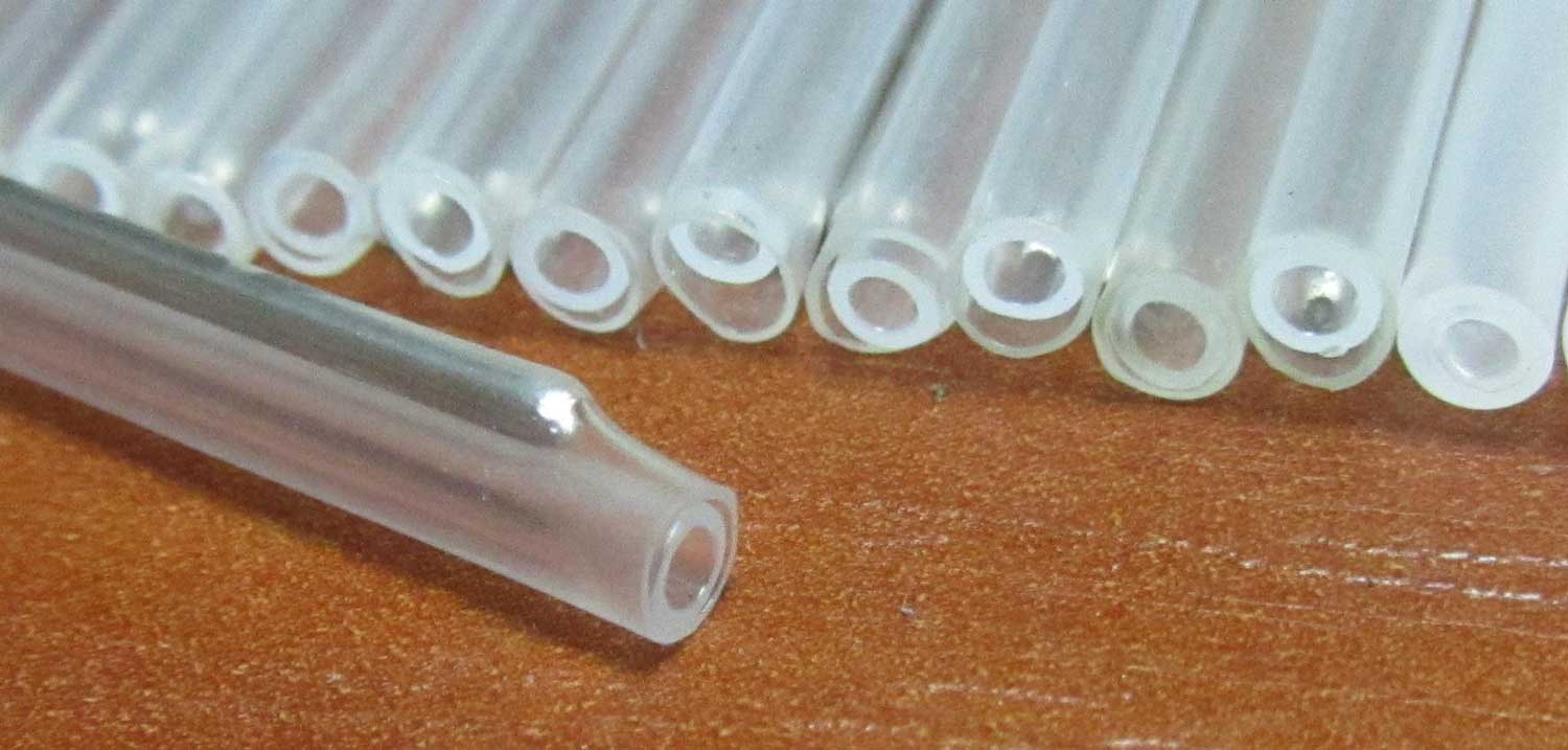
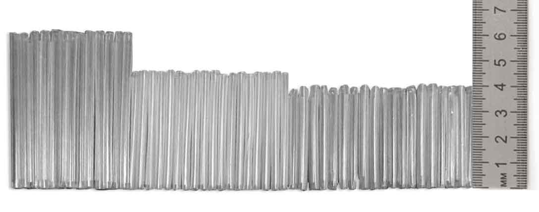
What is a transition tube? This is a regular polyethylene tube. In diameter, it is similar to a dropper tube and is made of plastic – polyethylene (the same as the rod of a sharpie pen, only the walls are thinner). They come complete with some splice closures. If you don’t have such a tube, you can replace it with some kind of shrink sleeve or even a dropper tube. It is not worth using a removed module instead of this tube: it is fragile, thin and has a lot of hydrophobic gel inside. You must not make fiber transition without a tube either: the optical fibers must be protected.
So, we have marked modules, measured fibers and thought out how they would fit into cable organizers. Next, you need to put fiber optic protection sleeves on, clean and fuse.
Here you can act in different ways. You may take a pair of optical fibers to be fused, put a protection sleeve on one of them, clean them, cleave, fuse and lay. Then you take the second pair, and so on. Another option would be as follows: first you should put protection sleeves on all fibers (or rather, half of them) – after all, one protection sleeve protects one splice, which involves two fibers); then all fibers are stripped with a stripper (but not cleaved or wiped with alcohol); and only then you look at the wiring map and begin to fuse. Fuse a group that is convenient to lay (usually one module) – and lay it. Fuse the second module and lay it, and so on. In doing so, we save time and are not likely to forget to put on a protection sleeve.
What is a FSPK or a protective sleeve? This is a disposable composite heat shrink sleeve that protects the splice.
They are sold in tens and hundreds of pieces, often come with fiber optic splice closures/ODFs, and are inexpensive. The abbreviation stands for Fusion Splice Protection Kit. It consists of 3 parts: a tube of readily fusible plastic inside, a plastic tube with shrink properties outside and between them iron wire for rigidity. The protective sleeves are put on one of the fibers to be fused (prior to fusion); when fibers are successfully fused, it is pushed to the splice site so that to completely hide the glass, and a slightly stretched fiber is put into the fusion splicer oven for about 20-40 seconds. In the oven, the inner plastic melts wrapping the fused fibers, and the outer plastic is heat shrunk.
FSPK (and, accordingly, optical cable organizers) come in different standards.
In the past, FSPK-60 were most often encountered; they are widely used even now. At present, fiber optic splice closures / ODFs with cable organizers designed for FSPK-40 or FSPK-45 are most popular. Such FSPKs are better: they require less time to shrink and take up less space in the cable organizer.
If the cable organizer is designed for FSPK-60, you can still put FSPK-40 there, but sleeves will hang out and you will need to fix them with the tape. With the cable organizer designed for FSPK-40 / FSPK-45, you can still cram FSPK-60, but this is fraught with the following consequences:
There are branded Fujikura FSPKs, which settle in a split second as opposed to 30-40 seconds for a conventional FSPK.
A good FSPK is tight, thin, monolithic, and neat. A poor FSPK is soft; it falls down about your ears into 3 components; after shrinkage it remains too thick and poorly fits; between the layers there are large cracks; therefore, when putting it on the fiber, you can by mistake miss the fiber between the inner and outer tubes, which is bad.
Only one pair of fibers should be laid into a single FSPK.
So, we labeled and measured fibers and FSPK on them. Now you can clean them from polyamide lacquer coating with a stripper.
Here everything is quite simple. The main thing is to do everything slowly and carefully so that not to break optical fibers: remember that fibers are measured and if you break such a fiber 2-3 times, it will become shorter and it will not normally fall into place where we meant it to fit. It is necessary to cut it off by about 3 centimeters; you should find the exact distance with a trial and error method and simply estimate by eye. At first, you can use a ruler to help you.
If you cut the optical fiber too much, then after the fiber has been cleaved, the remaining tip will be too short and the fiber container rollers may not be able to trap it. If you cut too little, then this cleaved tip will be so long that it won’t fit in the fiber container and will stick out of it. Both options are undesirable. However, if 2-3 splices in a row were unsuccessful (which sometimes happens even with flagship tools), the fiber becomes short and to save fiber it is necessary to cut it short deliberately, just enough for the cleaver to cleave. And the remaining tip can be put into the fiber container with tweezers or insulated with the electrical tape.
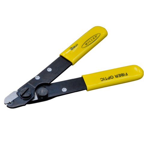
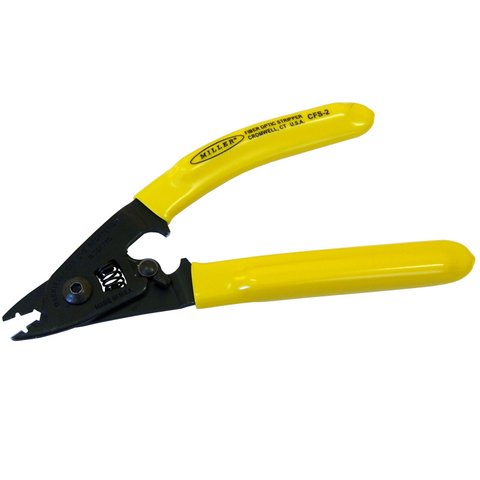
An optical stripper is a delicate and expensive tool. Its cut is strictly defined: it should completely remove lacquer from the fiber in one pass without damaging or splitting glass. So do not cut plastic ties with this stripper or what’s more, do not cut wires. It is designed only for cutting 125-micrometer fibers.
Finally, all fibers are marked, cut and equipped with FSPK. All the preparatory work is finished! You can remove unnecessary cutting tools from the table, wash your hands and proudly take out your main treasure – a fiber optic fusion splicer. We start fusing!
