
31.07.2023
This is the most high-tech part of your work. It is crucial that your hands are clean! Optical fiber fusion splicing usually takes a little less time than previous steps – cable punch down, splice closure / ODF preparation, and fiber preparation.
So, what do you need for fusion splicing? You will need to have the have following items at your disposal:
Turn on the fiber optic fusion splicer. If necessary, perform self-diagnostics, calibration, arc testing, baking of electrodes, etc.
Take the first fiber; wipe its glass part with alcohol cloth with effort several times on several sides (dragging the fiber through a folded wipe), turning by some angle at each pass to ensure that all dirt is removed. It is desirable to wipe the next fiber with a new napkin or wipe. If you decide to use the old one then the wipe should be unfolded and folded again so that it touches the fiber with it clean side. Do not unfold the wipe so that the fiber is in contact with the side you touched with your fingers. In general, the purity of spliced fibers is a crucial issue; it directly affects the quality of future fusion splicing and signal attenuation, so purity is the highest priority.
A clean fiber is inserted into the cleaver and is cut to the required length. Cleaving was discussed in an article about cleavers.
The cleaved fiber cannot be put anywhere, because it should be superpure.
Immediately after cleaving, the fiber is placed into the fusion splicer. Here it is important to put it in a V- groove so that you do not touch anything with the fiber end and so that no micro-dust from the groove gets to the fiber end. Insert the fiber neatly; then close the clamp of the movable carriage. It is important to lay the fiber so that its end protrudes at a couple of millimeters from the V-groove, but does not cross the middle part of the fusion splicer (an imaginary line between electrodes). An example of good fiber insertion is shown at the picture in the header to the first article.
If we insert fibers so that the fiber tip does not protrude from the V-groove, then there won’t be sufficient range for carriages to bring fibers together. If we insert them so that the tip crosses an imaginary line between electrode tips, then the splicer will have to bring apart fibers instead of bringing them together in order to detect their ends; there is no room for the carriage to move in the opposite direction, so the fusion splicer will display an error message.
Actions B, C and D are performed for fiber 2.
Press the button, and the optical fibers will be spliced automatically.
Different devices do the splicing a bit differently. In Fujikura, for example, the process can be fine-tuned, up to the current intensity in the arc and timings, but it's better to steer clear of these fine settings (the splicing equipment suppliers often block them). When splicing, pay attention to the arc shape (if the arc is curved and unstable, something is wrong: maybe it’s time to change electrodes or perform a calibration), check whether there are any defects in the splice. Good splice is practically invisible, or if it can be seen, you will notice a narrow – almost invisible – strip or slight fuzziness. The signs of poor splice can be a black bubble dot or a certain axial displacement of fibers, or a strongly visible dark strip across the fiber at splice, or other screw-ups. If splicing is seemingly high quality, but the fusion splicer displays expected attenuation that is too high (say, 0.1 dB), it is better to splice again. If your fusion splice is poor quality, you should perform splicing again. Even if you just have a slight doubt, it is better to redo it instead of relying on a bit of luck. Later on, you will definitely be unwilling to go and dig out the splice closure or remove it from the pole in order to fuse one bad fiber. An experienced technician can knowingly leave some screw-ups unattended: for example, a certain degree of fussiness of the splice usually means that some residual dirt melted and spread over the surface of fibers, or a small bubble may be formed not in the center, but at the edge of the fiber and not increase attenuation. However, it's better not to risk and redo the splicing.
Still, if your work object is large with dozens of splice closures / ODFs, there will always be something sticking out and you will need to do extra work. Also, it happens occasionally that the splice looks ideal on the fusion splicer display but then while testing it turns out that there is noticeable attenuation. This is because the camera-microscope cannot cover all 360 degrees around the fiber and the screw-up can sometimes hide in the camera blind zone.
Here are some examples of screw-ups that need to be redone.
 A big "bubble". Redo.
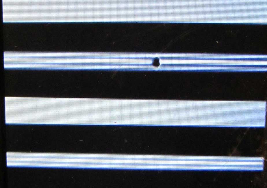 A small bubble. If it has not touched the core, there may be no attenuation in the splice, but if there is no measuring instrument with a reflectometer showing "It's OK, fuse on", you definitely need to redo the splicing.
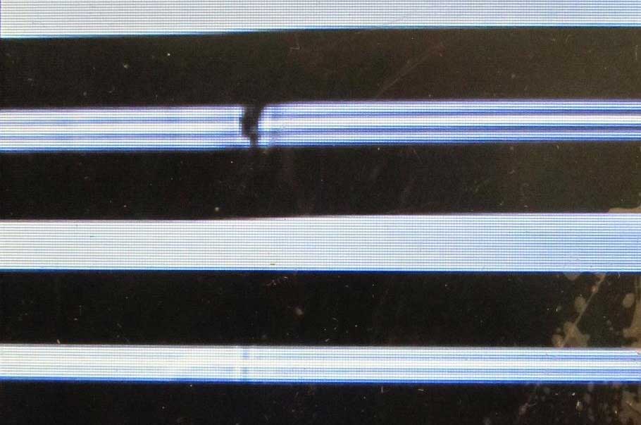 Some axial displacement of fibers + a kind of heterogeneity. Redo.
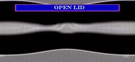 This happens if the arc was too long or the current was too high, or the splice came off badly. Redo.
 Here, it seems that convergence micromotors in the fusion splicer are faulty or not calibrated (fibers collided too strongly during the arc).
In general, if possible, it is best to fuse using a reflectometer for testing. For example, two operators are fusing, and the third person is at the nearest ODF controlling the splice quality with a reflectometer. If an unnoticed screw-up occurred, this person will immediately call operators asking to redo the splicing. The rule of the thumb is as follows: if signal loss at splice is 0.05 dB or more (at any wavelength – 1310 nm or 1550 nm), then the splice needs to be redone. If it is less than 0.05 dB, we keep the splice, put on protective sleeve and go on with splicing.
 Example of high quality splicing. A small strip or blotchiness, as in the photo, is generally undesirable, but it does not affect the level of attenuation statistically.
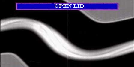
Sometimes it becomes necessary to splice an attenuator, that is, to fuse fibers with a certain signal loss. In such a case a special mode is selected, and the fusion splicer intentionally displaces one of the fibers at a few microns and splicing produces a slightly curved line.
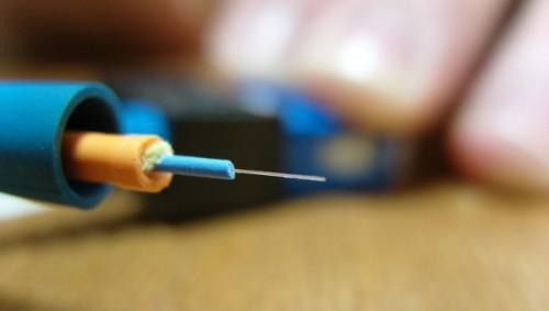
The spliced fiber is carefully pulled out of the fusion splicer and an protective sleeve (FSPK) is put on the splice. Until the protective sleeve is settled, the fiber is not protected and can be easily broken.
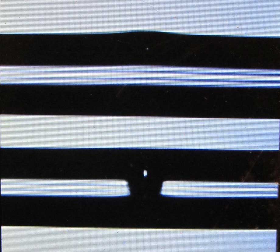
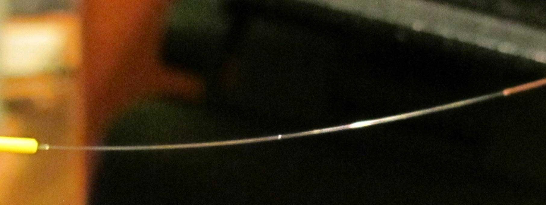 Spliced fiber (macrophotography). In the place of splice, there is a dot, which refracts light – this is normal.
After that, the fiber with the protection sleeve is placed in the oven of the fusion splicer so that the edges of the lacquer protective coating of both fibers were in FSPK, that is, after shrinking there are no sections with bare unprotected glass on the fiber. For the sleeve, a proper operating time of the oven should be set (use preset modes for FSPK-40 or FSPK-60).
The spliced and shrunk fiber is removed from the oven and placed in the cooling tray for about a minute. If the FSPK sleeve has not cooled down it cannot be placed in the cable organizer, since the plastic of the protective sleeve is still soft and the fiber inside the protective sleeve can be easily crushed, when you try to cram the protective sleeve into the cable organizer cradle. By the way, if you don’t take out protective sleeve from the oven immediately after the timer stops, it may stick to it. This is a common beginner's mistake, “I forgot to immediately pull out the protective sleeve, it got stuck, but has not completely cooled down yet.” The beginner begins to pick it out with tweezers and because of soft plastic the fiber breaks ... And without noticing this, he puts the protective sleeve in the cable organizer. If the protective sleeve is stuck in the oven, you can either tamper with it with something like a ruler, or pull it strongly upward straining fibers from both, or wait for it to cool down, and touch it with tweezers – it will easily peel off.
The spliced cooled fiber (or the whole spliced module) is put into the cable organizer.
You can lay fibers in various ways: you can either first put the protective sleeve into the cradle, and then lay the first and second eye of fibers, or start with one of fiber eye, after reaching the protective sleeve, place protective sleeve into the appropriate place and then lay the remaining length of fibers. In any case, you should be careful not to damage the fibers and lay the fiber neatly. If the fibers were not measured and cut before splicing, then after splicing, the fiber may be placed in the cable organizer inaccurately or not laid at all. When laying fibers it is very important to watch bending radii, not to allow too many kinks and blocks of fibers, since such bending will be a source of strong signal attenuation. If you have made a mistake in measurements and fibers are not placed normally, it is better to let them be glued to the cable organizer with a tape than be stretched on the turning points with strong bends.
After the fibers are laid, you should indicate on the cable organizer with inscriptions, arrows and curly brackets, the fibers direction. Also, it is possible to show with arrows and inscriptions the cable direction, or glue the labels indicating direction inside the splice closure. Similar tags, only waterproof, should be attached on the outside of the splice closure / ODF to the cable; these tags indicate the direction a cable takes, display the code of the communication line, its owner, etc. on at the request of the customer. It's also a good idea to put a copy of FO cable lay-out into the splice closure (although this is a controversial issue: a person who opens the splice closure legally should have the FO cable lay-out, and if someone opens the splice closure without a FO cable lay-out, then it's already abnormal).
After all the fibers are spliced in accordance with the fiber optic cable lay-out and laid, you can begin installing the splice closure and sealing (do not forget to take a picture of the splice closure if the customer requires it, and to put a package of silica gel into the splice closure). These operations are carried out in accordance with the instructions for assembling the FO splice closure. If cables are sealed with heat shrinkage, it is important to prevent the tube from overheating if they are shrunk using an industrial hot air gun or gas burner, because some heat shrink tubes may burst from local overheating. On some heat-shrink tubes (Tyco electronics, for example), there is a green dotted label, which disappears when the area is sufficiently warmed. If the heat shrink tube has burst, then you can put on a shrinkable sleeve, known as XAGA (if available) not to redo the work from scratch. Such a sleeve is a heat-shrinkable cloth with a hot-melt glue on one side and with "ribs" along the edges.
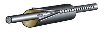
These sleeves come in different sizes. Some are suitable for sealing the cable entry to the splice closure; others can wrap the entire splice closure. Cutting off a piece of cloth, wrapping it around the cable with the adhesive side inward, aligning the sides and pushing the lock on them, we can get a regular heat shrinkage. Then heat it up using a hot air gun or a burner – the glue melts and the sleeve is positioned correctly. However, such a sleeve is relatively expensive.
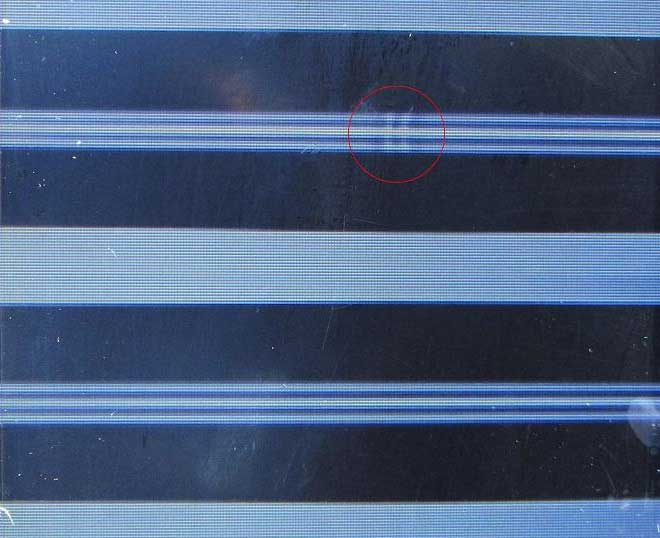
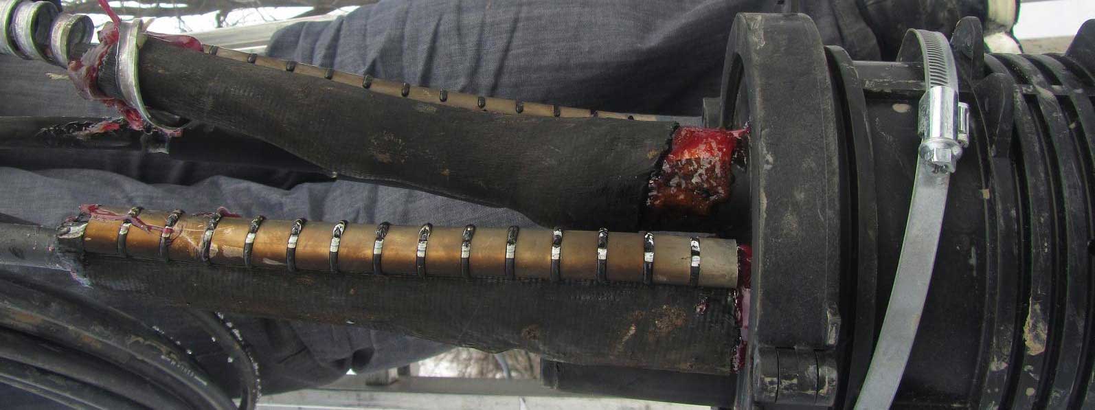 Two cables out of three included in the splice closure (one of fiber optic cables is at the bottom and the ground wire in the flexible metal hose is at the top) are sealed with a heat shrinkable sleeve. The upper cable is sealed a little carelessly: the sleeve half got off the cable bushing sleeve.
If the cables are cold-sealed, care must be taken to ensure the adhesion of the sealant to the cable, and it is necessary to follow the instructions. Faulty sealing of the splice closure is not permissible! Especially important is the sealing quality for splice closures installed in damp basements and wells where solid flooding is a possibility. Also, put a bag of silica gel (if included) in the splice closure so that the silica gel absorbs moisture from the air inside the splice closure. The assembled and sealed splice closure should be carefully positioned on its permanent place without breaking cables, and, if necessary, fixed. If the splice closure is supposed to be located on the pole (support), the cable slack is wound on a large iron crossbar, which was attached to the pole with steel tape earlier.
