RIGOL DS1102D Mixed Signal Digital Oscilloscope Review (Part 2)
In the second part of overview we'll cover more details regarding RIGOL DS1102D Mixed Signal Digital Oscilloscope functions and menu.
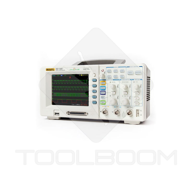
RIGOL DS1102D Dual-Channel Digital Oscilloscope Menu
The control over RIGOL DS1102D Digital Oscilloscope menu is provided using buttons and knobs. The menu is structured in two levels. User should get used to RIGOL DS1102D digital oscilloscope control as due to variety of options it takes some time to access some of them at first.
The MENU area of RIGOL DS1102D digital oscilloscope includes the following items:
- Measure – auto measurements;
- Cursor – cursor measurements;
- Acquire – data recording;
- Display – display;
- Storage – data saving;
- Utility – servicing.
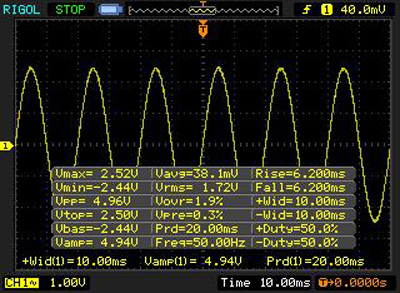
Measure menu
Measure menu can display up to 20 parameters of signal auto measurements. 10 of them are voltage parameters and the other 10 are time parameters. Each of parameters except for the caption one is graphically represented for user convenient orientation.
Measure menu view
| Main window | Voltage parameters | Time parameters | ||||
 |
 |
 |
 |
 |
 |
 |
Three parameters may be displayed simultaneously (bottom line). The next selected parameter appears on the right at the bottom, and the outside left one correspondingly disappears. All signal data may also be displayed by choosing the Display All menu item.
Cursor menu
Cursor menu allows conducting three types of signal detection:
- Manual
- Track
- Auto Measure.
Tracking function result represents the voltage and signal time difference.
Cursor menu view
| Manual | Track | Auto Measure |
 |
 |
 |
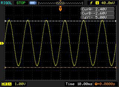
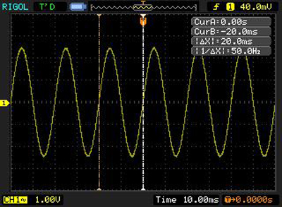
Parameters available in manual mode:
Amplitude growth
Time growth
In the tracking mode channels for cursor (A) and cursor (B) are to be chosen separately. As a result we obtain data on any waveform point.
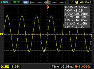
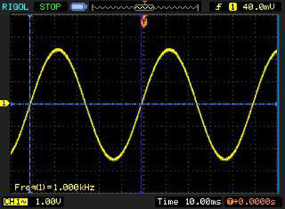
For starting the automatic measuring mode a certain parameter from the Auto Measure menu should be chosen. For example, for a frequency parameter the period will be marked with a cursor and signal frequency will be determined.
Acquire menu
Acquire menu allows adjusting the digital detecting system.
The first parameter of this menu is a data acquisition type (Normal Acquisition, Average Acquisition and Peak Detect Acquisition mode).
The second parameter is a real-time sample rate mode (Real Time) or equivalent sample rate mode (Equ-Time).
The third parameter is a memory selection: 512 K memory (dual channels) or 1 M (single channel) (Long Mem), 8 K memory (dual channels) or 16 K (single channel) (Normal).
Acquire menu view

Display menu
The following settings may be selected in Display menu:
- Waveform display type (vector or dot type).
- Clearing all waveforms from the display.
- Persistence (previous waveforms remain displayed on the screen until the persistence function is turned off).
- Display contrast.
- Display grid.
- Display brightness.
- Menu displaying time.
- Normal or inverted color display mode.
Display menu view


Storage menu
Storage menu allows:
- storing the files in the memory: signal forms, device settings, signal images (BMP files), signal parameters (CSV files);
- reading files from the memory: signal forms, device settings, initial settings.
Storage menu view
| Types of saved and read files | Removable disk menu | |||||
 |
 |
 |
 |
 |
 |
 |
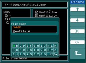
Screen of file saving and renaming in Storage menu
Utility menu
Utility menu provides the following settings:
- Input/output configuration
- Sound
- Frequency counter
- Menu language
- Pass/Fail parameter
- Waveform record
- Printout
- Settings
- Auto calibration
- System info
Tolerance test function Pass/Fail is one of the special functions of RIGOL oscilloscopes. On running this function RIGOL DS1102D digital oscilloscope automatically compares the input signal with a previously created signal form mask. If the signal form overruns the mask limits, the test result is Fail. Otherwise the test is passed. An audio alarm may be switched on in the settings, it will notify about the signal overrunning the mask limits. In the display left upper corner the amount of tested forms is shown: total, valid and faulty form numbers. A mode for this function may be set in the way that if signal overruns the mask limits the counting either will be continued (faulty forms will be counted) or stop right after the faulty signal form is detected.
Three modes with their settings are available in Storage menu:
Save mode
- recorded signal source setup (CH1, CH2, Pass/Fail-OUT);
- frame number setup (1000 max);
- signal detection interval setup (1 ms – 1000 s).
Load mode
- frame interval setup;
- first frame setup;
- last frame setup.
Memory import/export mode
- first frame setup;
- last frame setup;
- memory select (internal/external).
Utility menu view
 |
 |
 |
The following menus are located separately:
- Channel menu (CH1, CH2);
- Mathematical operations menu (MATH);
- Reference signal menu (REF);
- Trigger menu (TRIGGER).
CH1 and CH2 Channel menu
In channel menu (CH1, CH2) the following settings may be adjusted:
- channel communication type according to the current (AC, DC, GND);
- bandwidth (on/off);
- divider (1x – 1000x);
- digital filter parameters (LPF, HPF, band-pass filter, ejector filter);
- Volt/div (accurate/rough);
- signal inversion.
Math menu
Math menu provides four mathematical functions:
- Adding (A+B)
- Subtraction (A-B)
- Multiplication (A×B)
- Fast Fourier transform (FFT)
A few words about the fast Fourier transform
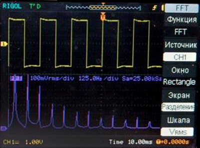
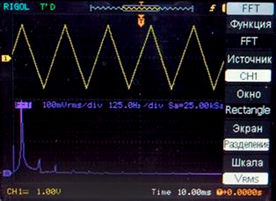
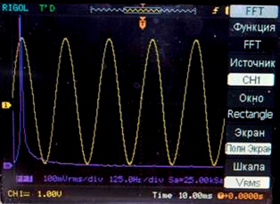
Fast Fourier transform (FT) is based on a very simple, though exceptionally fruitful idea – almost any periodic function may be presented as a sum of separate harmonic components (sinusoid and cosine curve with different amplitudes F, periods T and, consequently, frequencies ω).
The indisputable FT advantage is its flexibility – the transform may be used for both continuous time functions, and for discrete ones. In the latter case it is called the discrete Fourier transform – DFT.
Executing the DFT of the input sequence directly – strictly following the initial formula, will require a lot of time (especially if there is a large number of input indications). It is more constructive to use divide and rule principle laying in the basis of the DFT algorithm. According to it the input sequence is divided into groups (e.g. even and odd counts), and the DFT is conducted for each of them, and then the obtained results are merged. As a result we have an input sequence DFT, and a significant time saving. That is why the described algorithm was named the fast Fourier transform.
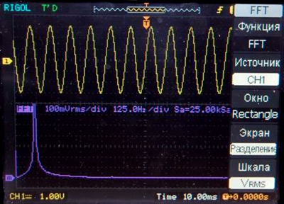
DFT examples for some of the standard signal forms with separate displaying
Sinusoid
Meander
Saw-toothed
DFT example for the sinusoidal signal form with simultaneous displaying
REF menu
REF menu – using the reference signal
Reference waveforms are the waveforms which are stored in the memory and may be displayed. Reference signal function is available after saving the selected waveform into the nonvolatile memory.
REF menu view
Internal and external memory use |
 |
HORIZONTAL zone menu
The following parameters are set in the horizontal time base menu:
- Fragment increase mode (on/off)
- Display mode selection (Y-T, X-Y, Roll)
Y-T – displaying the dependence of the voltage (Y axis) from time (X axis).
X-Y – displaying the dependence of CH2 value on the Y axis from the CH1 value on the X axis. This format is useful for investigating the phase relation of two signals.
Roll – auto recorder mode, when the waveform is refreshed on the screen from the right to the left.
TRIGGER zone menu
Trigger system sets the reference time of the data detection and signal form displaying by digital oscilloscope. The correct trigger system setup ensures fine waveform displaying and stable signal form displaying. Until the trigger moment the oscilloscope continuously records and saves a certain data amount enough for signal form displaying to the left from the trigger point. After trigger conditions execution the oscilloscope continues recording and saving the data for signal form displaying to the right from the trigger point.
TRIGGER zone includes one knob and three buttons:
- LEVEL knob – a knob setting the trigger level, pressing its handle leads to setting a zero trigger level.
- 50% button – special button with a single function, pressing which leads to setting the trigger level to the middle point of trigger signal vertical swing.
- FORCE button – special button leading to the forced triggering, i.e. the oscilloscope takes it as fulfillment of trigger conditions. It is used mainly for oscilloscope setup under the normal and one-shot trigger modes.
- MENU button – a button for displaying the trigger system control menu.
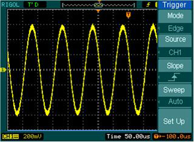
TRIGGER menu view
Trigger modes
RIGOL DS1102D dual-channel digital oscilloscope provides 7 trigger modes:
- Edge: triggering by edge occurs when the input signal crosses the selected voltage level in the selected direction (rise, fall of random edge).
- Pulse: triggering by pulse duration; this trigger mode is used to detect pulses of certain duration.
- Video: triggering by video signal is used for triggering by fields or lines from line-synchronizing pulse of the standard video signals. It is worth mentioning about the video signal polarity mode, even and odd half-frame selection for frame synchronization.
- Slope: triggering by the rate of rise is conducted by oscilloscope on executing the set conditions on duration and on the level of the rising (falling) signal edge. Such a solution is used in the oscilloscopes of this price range for the first time.
- Alternate: by turn triggering from CH1 and CH2 channels for simultaneous observation of two nonsynchronized signals.
- Pattern: triggering by certain logic signal pattern.
- Duration: triggering by matching with certain logic signal pattern during a set time interval.
RIGOL DS1102D Dual-Channel Digital Oscilloscope Package Contents
RIGOL DS1102D Mixed Signal Digital Oscilloscope package contains everything needed for operation. The nozzles for analogue test leads and digital analyzer contacts are equipped with special clamps. Using them allows catching hold of the IC leg or any other electronic circuit contact.
Package contents:
- RIGOL DS1102D digital oscilloscope unit;
- Test leads with long head 10:1 (testers);
- Connector with 16 signal outputs and 2 GND inputs;
- Cable for connector connection with digital analyzer;
- Nozzles for test leads (2 pcs.);
- Alligator clips for test lead grounding (2 pcs.);
- Connector contact tips (18 pcs.);
- CD with software;
- USB cable;
- Power cable;
- Precision test lead nozzles;
- Short manual.
Conclusions
RIGOL DS1102D Mixed Signal Digital Oscilloscope provides a unique combination of functional characteristics, reliability and price. Its features amaze: multiple functions, trigger modes, data acquisition and analysis, comfortable interface. The price of RIGOL digital oscilloscope model of such class is significantly lower compared to that of oscilloscopes from the market leaders Agilent Technologies and Tektronix. Besides, the company gives an unprecedented warranty for its products (3 years). RIGOL digital oscilloscopes undergo hard hours-long thermal testsin order to minimize the probability that defective products would reach the market.
USB interface of RIGOL DS1102D digital oscilloscope enables microcode update, computer connection and saving files on a flash drive.
It is the first time when a popular-price digital oscilloscope is equipped with a built-in logic analyzer providing possibility of simultaneous displaying logic and analogue signals.
The built-in reference rectangular pulse (meander) generator of RIGOL DS1102D digital oscilloscope enables the unassisted calibration of testers, if needed.
The quality of RIGOL digital oscilloscopes assembling is worth positive appraisal. The company does not yield to the acknowledged manufacturers in this issue.
Sergiy Safonyuk,
Technical expert of ToolBoom Online Store
First part of RIGOL DS1102D Mixed Signal Oscilloscope Review
