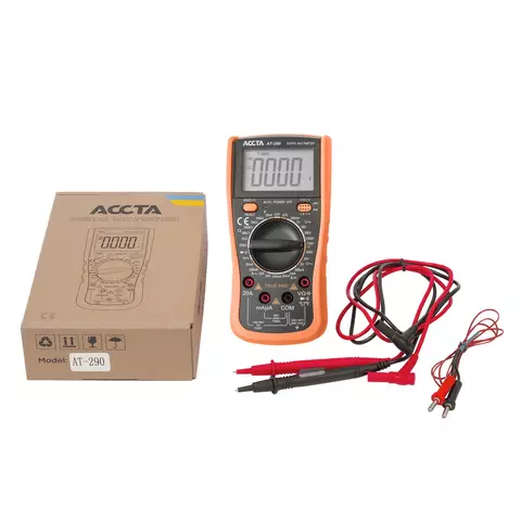
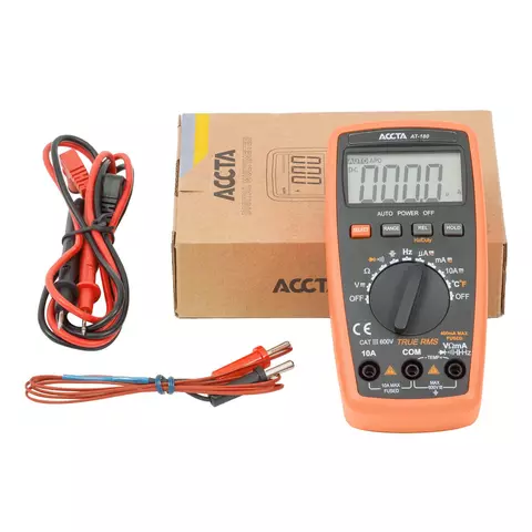

True RMS digital multimeter which measures AC/DC voltage, AC/DC current, resistance, capacitance, temperature and can be used for continuity, transistor and diode tests.
Availability in stock:
HK
ID: 891501 0.65 kg
When inexperienced (and experienced :-) electrical engineers or just radio amateurs test electronic devices, they often need to test radio components soldered on PCB. In our experience, one of the common failure causes is capacitor faults. In fact, one can find a vast deal of web resources on testing capacitors. However, to save your time we have prepared an article for our customers. In this article, we have selected and further explored best options that will help you test your capacitor competently and fast.
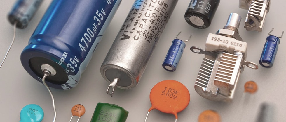
For an initial test, you can easily do without using test & measuring equipment – you just need to visually check whether the capacitor is in good condition. The main indicators of its failure are as follows:
If you see any of these, you need to replace the capacitor with a new one immediately. If there are no visible signs of capacitor failure, then proceed to the next testing stage using such test & measuring tools as an RLC meter or a multimeter with resistance & capacitance measuring functions.
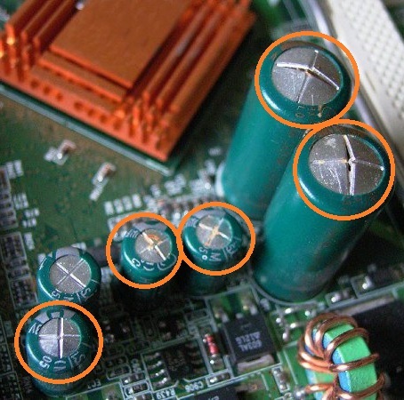 Bulging of the vent on top of the capacitor
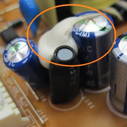 Electrolyte leakage
To test a capacitor competently, you need to know that capacitors can be of two types:
When testing polarized capacitors, be sure to connect the multimeter probes properly (connect the capacitor positive lead to the positive probe, and the negative lead to the negative probe). In most cases, the polarity is marked on the casing. It is also important to desolder the capacitor from the PCB (completely or partially), since adjacent components could affect the accuracy of measurements. After that, you need to fully discharge the capacitor. For this purpose, you can use a metal object, such as tweezers or a screwdriver. High-voltage capacitors are better discharged using some electrical device, for example, an electric bulb. When testing, do not touch probes with your fingers, because the human body electrical resistance may lead to inaccuracy in measurements.
Before starting a test, let’s determine main failure modes, that is, types of faults that can occur in a capacitor:
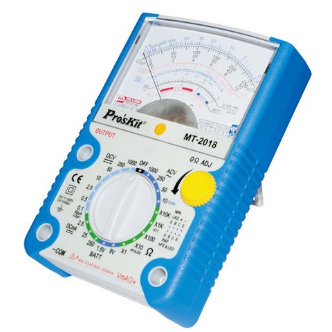
When the operating voltage of a capacitor exceeds its nominal value, it will lead to the breakdown (of insulation) between its plates. As a rule, this results in mechanical damage, but not always. You can check whether there is breakdown when measuring resistance. Connect the probes to the capacitor leads (for a polarized capacitor, keep their polarity in mind). If there is dielectric breakdown, the resistance value will be zero or close to zero. If the capacitor operates OK, it will show some resistance value on the multimeter display, which will gradually grow, without surges. It is easier to check non-polarized capacitors – you set resistance to at least 2 MΩ on a multimeter, and the polarity of probes doesn’t matter. Why choose this resistance range? The fact is that resistance in a non-operating capacitor is rarely higher than 2 MΩ. Also, analog (pointer) multimeters come in handy when testing resistance in capacitors. Their measurement principle is the same as described above, and additionally, the pointer allows you to clearly observe gradual change in resistance and control the process of charging the capacitor based on the pointer readings.
The loss of contact occurs when one or both capacitor leads separate (disconnect) from its plates. In this case, the capacitor doesn’t charge when the multimeter is testing resistance, and its capacitance equals zero.
To check whether the electrical component’s capacitance is decreasing, you need a digital multimeter that can measure capacitance. You can make measurements using ordinary probes or a special connector pin on the device housing (if such a pin is designed into the multimeter). You need to set a measurement range corresponding to the capacitance of the capacitor or use a multimeter with automatic range selection. Connect the capacitor to the probes / connector pin of the multimeter. Don’t forget about polarity. The capacitance tolerance is up to 30% of its nominal value.
Current leakage in a capacitor occurs when dielectric between its plates is not perfect. In normal operating conditions, it is insignificant, but when the current leakage increases, this electrical component loses its capacity to hold the charge. You can perform an overall assessment of current leakage using a conventional multimeter. To do this, you need to charge the capacitor from the power source and measure voltage on its leads at regular intervals. The faster voltage falls, the bigger current leakage is. You need a multimeter with an input impedance of DC voltage of at least 10 MΩ to ensure higher precision.
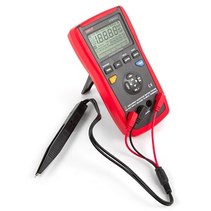
It may happen that a capacitor should seemingly operate OK judging from its look and specifications, but the device doesn’t work de facto. In this case, you can either just replace it with a new one or use a more advanced tool, an RLC meter, to measure the capacitor’s equivalent seriesl resistance (ESR). If ESR value increases, it leads to capacitor being additionally heated, which adversely affects its qualities and significantly reduces the service life. The main advantage of an RLC meter is that you can set the frequency at which the check is performed. This is especially important when testing high-frequency capacitors in switching DC power supply units and when testing low ESR capacitors. An estimate of admissible ESR is made by either comparing its value to the ESR value in a new capacitor of this type, or using a table with approximate values for different electrolytic capacitors, e.g., Bob Parker's ESR Chart.
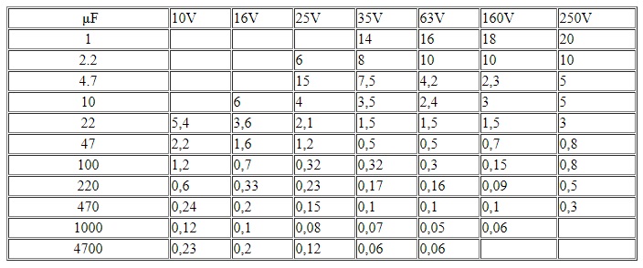 Bob Parker’s ESR chart
In short, there is nothing too complex about testing capacitors. Besides, a capacitor loses its properties to accumulate energy over time. Therefore, it is desirable to periodically check radio components in electronic devices; this can ensure their reliable and high-quality operation for many years. Our online store offers a wide range of multimeters and RLC meters to help you with it. If you have additional questions on choosing the test mode or on the procedure per se, please contact our technical support team, we will gladly help!
Do you enjoy reading our articles? If so, you have to check out our videos on this topic!