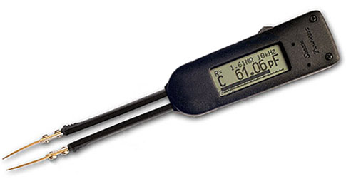
Smart Tweezers: High-Precision RLC-Meter
First Impression
Incredibly convenient, once you try Smart Tweezers, feels like you have been using it forever.
- light weight – small size (0,15 kg)
- Low cost
- Autonomous power supply
- Wide measurement range
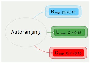
- Automatic recognition of the:
- measurement component (R/C/L)
- sampling frequency
- measurement range
- measurement units
- equivalent circuit
- SMD components testing
- Simultaneous Display of Active and Reactive Impedance Components
- Measurement speed selection
- Analog Bar Graph
- Manual and voltage test modes
- Digital oscilloscope like display for AC voltage measurements
- Diode polarity/integrity tests
Smart Tweezers General Overview
Smart Tweezers (ST) is a portable impedance measuring device. ST is capable of measuring resistance, capacitance or inductance over a range of 8 orders of magnitude. The device exhibits the basic accuracy of 1% (resistance) and operates at 4 test frequencies (10kHz/1.0kHz/100Hz/120Hz).
Measuring Voltage and Current
The voltage is applied to the device under test (DUT) through the source resistance Rs. Current flows to the virtual ground of the current amplifier AI, and through the current conversion resistor Ri. The output of AI provides a signal proportional to the current, I*Ri.
Voltage across the DUT is measured by a separate signal path (amplifier AU), thus providing a pseudo 4-wire Kelvin connection.
Voltage and current signals are processed by the A/D converter. Obtained values are then corrected using calibration factors, converted to impedance and sent to the display.
Navigating Menus
It couldn't have been simpler! Turn Jog Dial to move the Selected Item cursor to the desired menu item and push Jog Dial to select the item.
- The Reset Button resets the unit. This may need to be pressed after changing the batteries.
- The Virtual Ground Connector is used when performing in-circuit measurements to eliminate the influence of grounded components, which requires connection to the circuit Ground
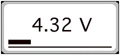
- The Slide Switch can optionally be used to measure DC voltage from 800mV up to 8V by enabling a 1/10 voltage divider.
ST Screen
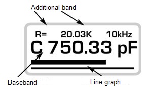 ST screen is divided into several displays.
- Primary Display
- takes up the middle of the screen
- Displays:
- the dominant parameter reading (e.g. "C")
- up to 5 digits
- measurement units
- Secondary Display
- takes up the top of the screen, the font displayed being smaller
- Displays:
- "H" is displayed if the Hold mode is on
- equivalent series and parallel resistance/ quality factor/ dissipation factor
- frequency of the generated impulses
- Bar Graph
- is located at the bottom of the screen
- provides the analogue representation of the measured major parameter value
- can be used to visually compare components with similar parameters.
The Display setting can be used to change the display orientation, contrast and the timeout
Display Parameters
 Resistance
- The Primary Display showing R [mΩ, Ω, kΩ, MΩ]
- sound Tone mode
range number of beeps 1-10 Ω 1 10-20 Ω 2 20-30 Ω 3 30-40 Ω 4
- L + R
- The Primary Display showing L [µH, mH, H]
- The Secondary Display showing R [mΩ, Ω] (the equivalent series resistance - the real part of impedance)
- L + Q
- The Primary Display showing L [µH, mH, H]
- The Secondary Display showing Q (quality factor, the imaginary/real part of the impedance ratio). A good inductance has a large L and a small R, therefore, a high Q.
- C + R
- The Primary Display showing C [pF, nF, µF]
- The Secondary Display showing R [Ω, kΩ] (equivalent series resistance is the real part of the impedance)
- C + D
- The Primary Display showing C [pF, nF, µF]
- The Secondary Display showing D (dissipation factor the real/imaginary part of the impedance ratio). A good capacitor has a large C and a small R, therefore, a low D.
Note
| range | optimal test frequency |
|---|---|
| < 10000 pF | 10 kHz |
| 1001 pF - 1 µF | 1 kHz |
| > 1 µF | 100 Hz |
High test frequency allows for lower offset when measuring low capacitance and inductance values, low test frequency decreases the offset value for higher capacitance and inductance. If the frequency is high the resistance becomes inductive, causing o0ffset. The Auto mode provides best results on the inductance values from 5µH up to 1kH. The table features optimal test frequency for different inductance values.
| range | optimal test frequency |
|---|---|
| < 10000 pF | 10 kHz |
| 1001 pF - 1 µF | 1 kHz |
| > 1 µF | 100 Hz |
The Auto mode is adapted for the measuring capacitance from 4 pF to 4999 µF. The table features optimal test frequency for different capacitance values.
Corrections for calculations on low resistance and capacitance values can be found in the manual.
Additional Measurement Options (apart from RLC)
- Diode mode. If the diode is shorted a resembling message "SHORT" is displayed.
- Input voltage range is -/+8V. Possible calibration and sampling rate change for higher
precision (system->service->offset):
- In the AC mode polarity (digital and analog value)
is displayed.
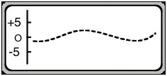
- In the Trace mode the user gets an oscilloscope
picture.
- In the AC mode polarity (digital and analog value)
is displayed.
You may be also interested in other products like digital multimeters or frequency counters.